Eureka AIR delivers breakthrough ideas for toughest innovation challenges, trusted by R&D personnel around the world.

Hydrogen Generation System, Method for Generating Hydrogen Using Solid Hydrogen Fuel and Method for Providing Hydrogen for Fuel Cell Using the Same

a hydrogen generation system and solid hydrogen fuel technology, applied in hydrogen production, electrochemical generators, chemistry apparatuses and processes, etc., can solve the problems of difficult to sustain the temperature of the hydrogen generation apparatus, fuel cell cannot generate the maximum power, and the mechanical design of the hydrogen generator is complicated and bulky, etc., to achieve the effect of stabilizing the hydrogen releasing reaction ra

Inactive Publication Date: 2011-06-16
IND TECH RES INST
View PDF37 Cites 12 Cited by
  • Summary
  • Abstract
  • Description
  • Claims
  • Application Information

AI Technical Summary

Benefits of technology

The patent describes a hydrogen generation system and method using solid hydrogen fuel, an absorbent material, and a phase-change material. The system uses the phase-change material to maintain a constant temperature and stabilize the reaction temperature for the hydrogen releasing reaction. This results in a controlled hydrogen releasing rate and stable hydrogen flow. The method involves mixing solid hydrogen fuel with absorbent material and a liquid, and using the phase-change material to absorb and store the reaction heat generated from the hydrogen releasing reaction. The generated hydrogen can then be used to fuel a fuel cell. The technical effects of this patent include improved hydrogen generation and stabilization of the hydrogen releasing reaction.

Problems solved by technology

It is not easy to sustain the temperature of the hydrogen generation apparatus at which the hydrogen-releasing reaction occurs at a certain value or range.
The fuel cell could not generate the maximum power if the hydrogen generation system of the fuel cell provides hydrogen gas with the hydrogen-releasing rate under the demand.
However, it would be energy waste that the hydrogen-releasing rate of the hydrogen generation system is higher than the standard value required for the fuel cell.
This hydrogen generator has a very complicated mechanical design with a bulky dimensions and weight, is, which is expansive and not easy to carry for daily use.
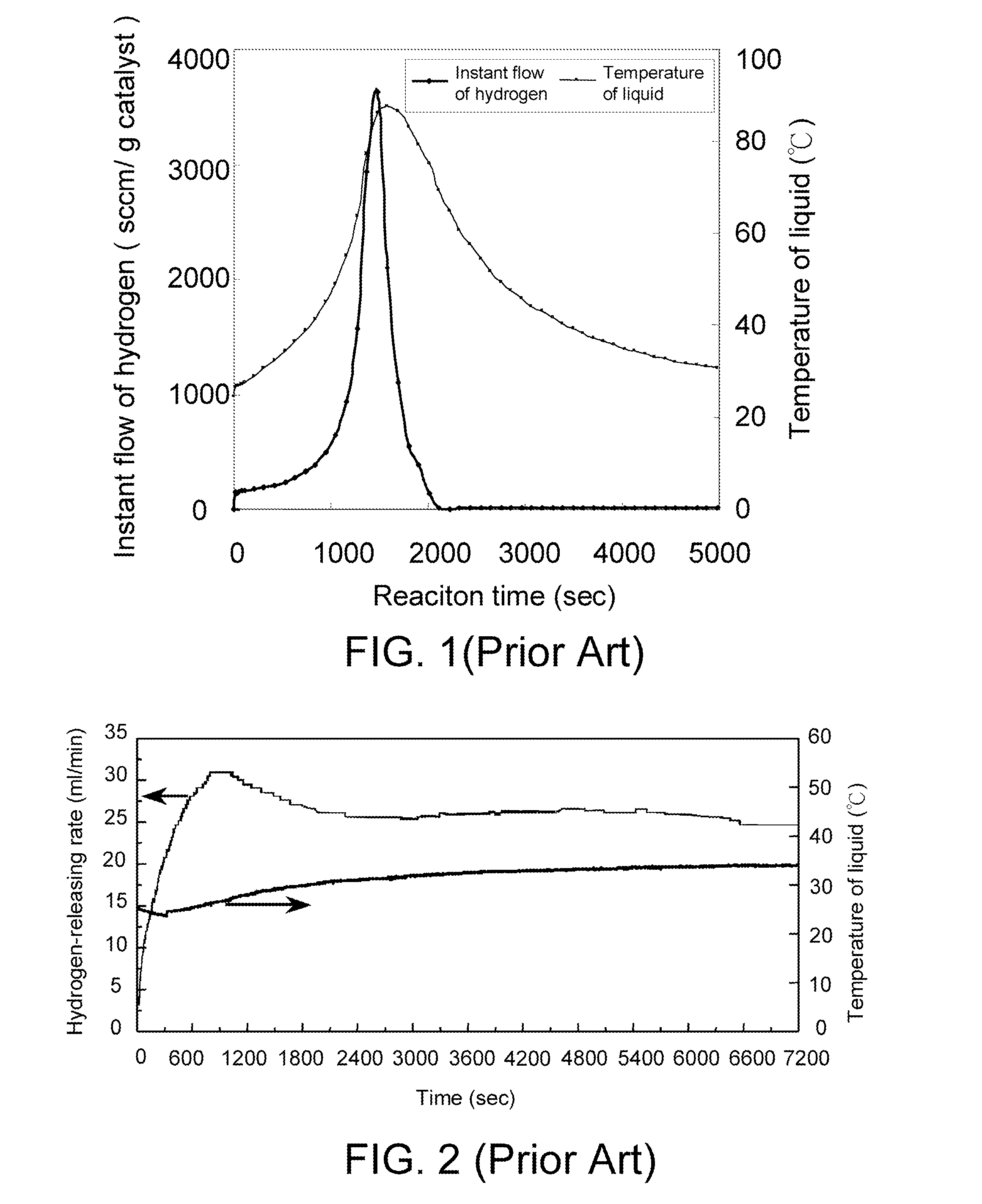
However, solid water such as gel-forming water could not rapidly absorbs the heat generated from the hydrogen releasing reaction, so that the hydrogen releasing rate of the reaction is varied (with the increasing temperature) and could not be sustained at a certain value, as shown in FIG. 3.

Method used


Image

  • Hydrogen Generation System, Method for Generating Hydrogen Using Solid Hydrogen Fuel and Method for Providing Hydrogen for Fuel Cell Using the Same
  • Hydrogen Generation System, Method for Generating Hydrogen Using Solid Hydrogen Fuel and Method for Providing Hydrogen for Fuel Cell Using the Same
  • Hydrogen Generation System, Method for Generating Hydrogen Using Solid Hydrogen Fuel and Method for Providing Hydrogen for Fuel Cell Using the Same

Examples


first embodiment

[0039]In an embodiment, a hydrogen generation system, capable of generating hydrogen for a fuel cell, comprises a solid hydrogen fuel, an absorbent material, a phase-change material and a liquid such as water, alcohols (ex: methanol or ethanol) or aqueous solutions thereof. The absorbent material is mixed with the solid hydrogen fuel and absorbs the liquid such as water, alcohols and aqueous solutions thereof, aqueous solutions of salts, or aqueous solutions of acids. The phase-change material is disposed adjacent to a position at which a hydrogen releasing reaction occurs. The phase-change material absorbs and stores the reaction heat generated from the hydrogen releasing reaction reacted by the solid hydrogen fuel and the liquid, so as to maintain a reaction temperature. Consequently, a hydrogen releasing rate of the hydrogen releasing reaction is controlled and a hydrogen flow is stabilized.

[0040]In the first embodiment, the phase-change material, the solid hydrogen fuel and the ...

second embodiment

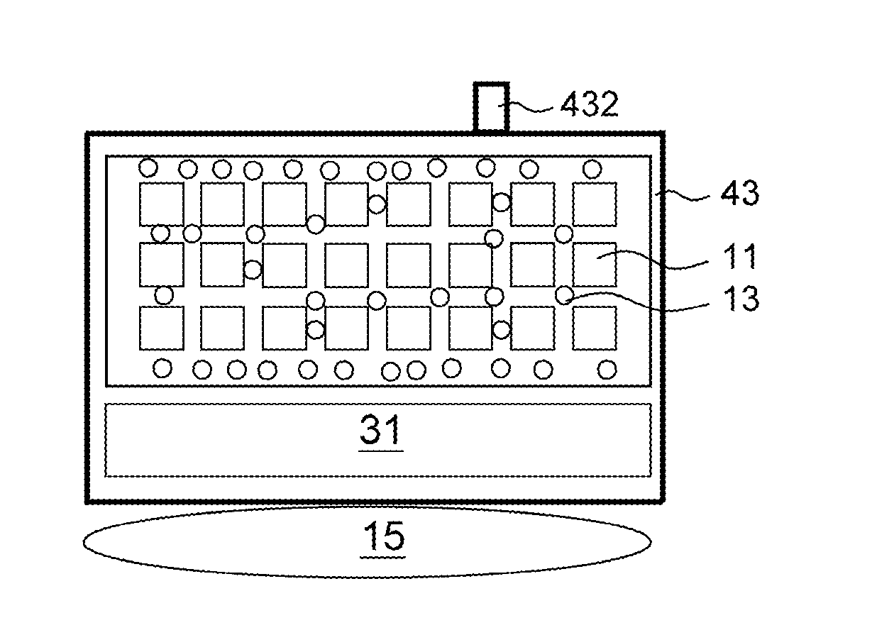
[0051]FIG. 5 illustrates a hydrogen production system with the solid hydrogen fuel according to the second embodiment of the present disclosure. The system composition of the second embodiment is identical to that of the first embodiment. The hydrogen releasing apparatus 43 of FIG. 5 has a fuel pack and a liquid package 31. However, only a mixture of the solid hydrogen fuel 11 and the absorbent material 13 is disposed in the fuel pack. The phase-change material 15 is disposed outside the fuel pack and directly contacts a container at which the fuel pack is placed (i.e. the hydrogen releasing apparatus 43). The phase-change material 15 is used for absorbing and storing the reaction heat generated from the hydrogen releasing reaction via heat conduction. Please also refer to the descriptions in the first embodiment for the compounds of the solid hydrogen fuel and the process for hydrogen releasing reaction in details.

[0052]Similarly, the hydrogen production system of the second embodi...

experiment 1

Relative Experiment 1

[0055]Please also referred to FIG. 4. 4 g of the flexble solid hydrogen fuel, comprising 2 g of NaBH4 (solid hydrogen powder), 0.4 g of cobalt ion catalyst (Co2+ / IR-120, solid hydrogen releasing catalyst) and 1.6 g of silicone subber (i.e. molding agent), is divided into 96 pieces and blended with the absorbing polymer (absorbent material); then, the phase-change material Na2SO4. 10H2O is added into this mixture for manufacturing a fuel pack. A liquid package is provided by adding water into a plastic bag with enclosure. The fuel pack and the liquid package are disposed into a hydrogen releasing apparatus. Afterwards, water in the liquid package is conducted into the fuel pack by piercing the plastic bag, and the hydrogen releasing rate is measured. FIG. 7A shows the hydrogen releasing curves of the solid hydrogen fuel, using Na2SO4.10H2O as the phase-change material, according to the embodiment of the present disclosure. FIG. 7B shows the enlarged hydrogen rele...


PUM

PropertyMeasurementUnit
temperatureaaaaaaaaaa
flexibleaaaaaaaaaa
hydrophobicaaaaaaaaaa

Abstract

A hydrogen generation system comprising solid hydrogen fuel, a liquid absorbent material, and a phase-change material is provided. When the liquid (usually water, alcohol, or aqueous solution of alcohol, aqueous solution of salt or aqueous solution of acid) in the absorbent material contacts with the solid hydrogen fuel, the solid hydrogen fuel will react with the liquid to release hydrogen and generate heat. The heat as generated will accumulate to increase the reaction temperature, and then boost the hydrogen-releasing rate. The phase-change material is adjacent to the solid hydrogen fuel for absorbing and storing the reaction heat, so as to stabilize the reaction temperature. Therefore, the hydrogen-releasing rate is kept as constant to achieve a steady hydrogen flow.

Description

[0001]This application claims the benefits of U.S. provisional application No. 61 / 285,467, filed Dec. 10, 2009, and Taiwan application Serial No. 099113137, filed Apr. 26, 2010, the subject matters of which are incorporated herein by reference.BACKGROUND[0002]1. Technical Field[0003]The disclosure relates in general to a hydrogen generation system, and more particularly to the hydrogen generation system capable of providing hydrogen to a fuel cell at a stabilized hydrogen-releasing rate.[0004]2. Description of the Related Art[0005]Fuel cell is a device capable of converting chemical energy into electrical energy. The fuel cell can generate electrical energy continuously while fuel and oxidant are provided constantly. As to the hydrogen fuel cell, the fuel is hydrogen, and the oxidant is oxygen.[0006]Take a conventional hydrogen production system in a hydrogen fuel cell and sodium borohydride (NaBH4) solution used as hydrogen source in the hydrogen production system for example. A pu...

Claims


Application Information

Patent Timeline
Patent Type & Authority Applications(United States)
IPC IPC(8): H01M8/06B01J8/00C01B3/02C01B3/08
CPCB01J7/02C01B3/065C01B2203/066Y02E60/362H01M8/065Y02E60/50H01M8/04216Y02E60/36
Inventor HSUEH, CHAN-LIKU, JIE-RENCHEN, CHENG-YENJENG, MING-SHANTSAU, FANG-HEI
Owner IND TECH RES INST
Why Eureka
Eureka Blog
Learn More