
Method and apparatus for motional/vibrational energy harvesting via electromagnetic induction using a magnet array

a technology of electromagnetic induction and electromagnetic induction, which is applied in the direction of electrical apparatus, dynamo-electric components, dynamo-electric machines, etc., can solve the problems of affecting the performance of the miniaturized device, and often nw-w level, etc., to achieve good shielding and large voltage

Inactive Publication Date: 2011-06-16
UNIV OF FLORIDA RES FOUNDATION INC
View PDF21 Cites 42 Cited by
  • Summary
  • Abstract
  • Description
  • Claims
  • Application Information

AI Technical Summary

Benefits of technology

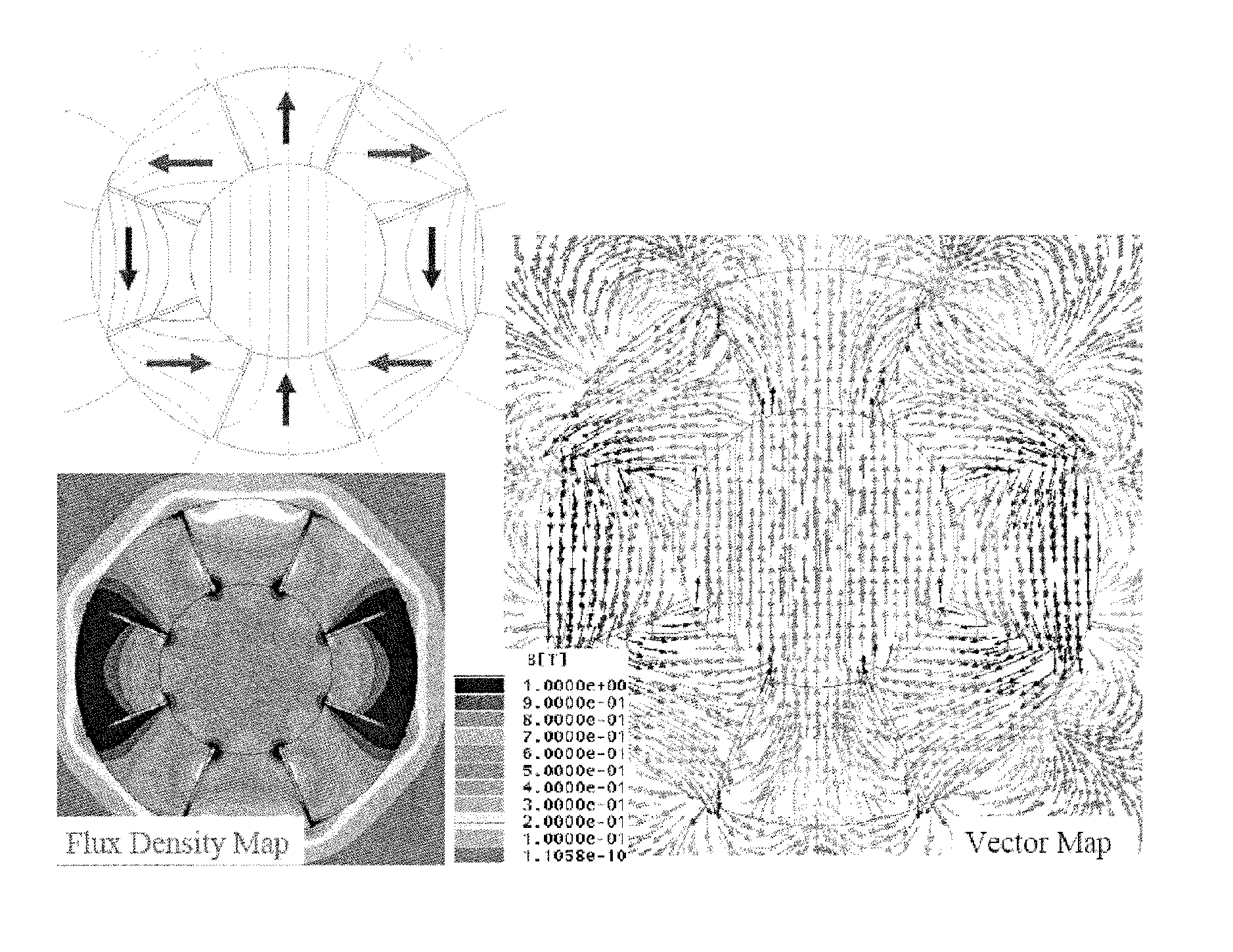
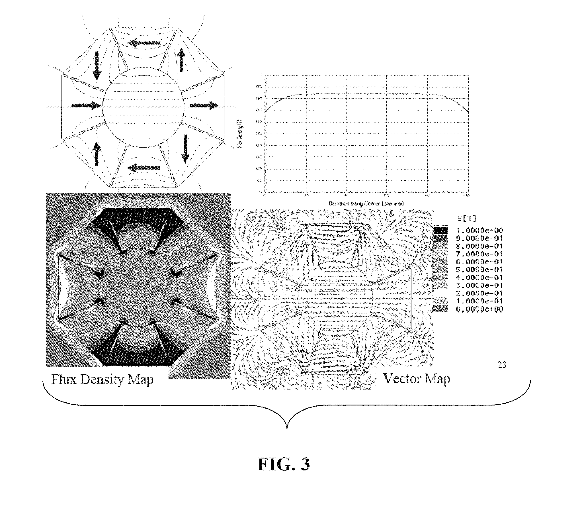
[0007]Specific embodiments of the subject invention can use a magnet array, such as Halbach array. A specific embodiment can use a Halbach cylinder type Halbach array. Halbach arrays used in conjunction with the embodiments of the invention can incorporate ferromagnetic material and establish strong magnetic fields, while also largely retaining these magnetic fields inside the device. Multi-Telsa fields can be accomplished within the device. Accordingly, use of a Halbach array, such as a Halbach cylinder, as a magnet array allows for large voltage induction, while providing good shielding for the magnetic induction energy harvesters.

Problems solved by technology

For example, micromachining and micro-electro-mechanical system (MEMS) technologies have been used to produce sub-millimeter microchip-sized devices, but the power output from these miniaturized devices has been very low (often nW-μW level), which appears to be too small to power many practical devices.
Most electromagnetic vibrational energy harvesters suffer from weak magnetic fields, which ultimately hampers their performance.
Unfortunately, the introduction of these soft magnetic cores to the open-field configuration can lead to high attractive magnetic forces, which may negatively impact the motion of the magnet in the configuration.
Introduction of soft magnetic cores can also cause the magnet to no longer readily move under external vibration.
Practical implementation of these magnetically-based vibrational energy harvesters can also be difficult as the static stray magnetic fields are difficult to shield.
Accordingly, magnetically based energy harvesters also tend to be magnetically attracted to ferrous objects external to the harvester, which may interfere with the harvester's operation.
Another potential issue with these harvesters is that the magnetic fields can adversely affect surrounding structures.

Method used


Image

  • Method and apparatus for motional/vibrational energy harvesting via electromagnetic induction using a magnet array
  • Method and apparatus for motional/vibrational energy harvesting via electromagnetic induction using a magnet array
  • Method and apparatus for motional/vibrational energy harvesting via electromagnetic induction using a magnet array

Examples


Embodiment Construction

[0026]Embodiments of the subject invention relate to a method and apparatus for producing an electric current. Embodiments of the subject invention also pertain to a method and apparatus for motional / vibrational energy harvesting via electromagnetic induction. Specific embodiments relate to non-resonant motional / vibrational energy harvesting.

[0027]Embodiments of the subject invention pertain to a method and apparatus for vibrational energy harvesting via electromagnetic induction using a magnet array. Specific embodiments of the subject invention incorporate at least one conductive coil and at least one magnet array. Magnets used in such magnet arrays can be permanent magnets of various shapes, such as arc-shaped, square, rectangular, wedge, or trapezoidal. These magnet arrays can then be, for example, circular, hexagonal, rectangular, or square in external shape and create various types of internal magnetic fields, such as dipole, quadrupole, hexapole, or octapole magnetic fields. ...


PUM


Abstract

Embodiments of the subject invention pertain to a method and apparatus for vibrational energy harvesting via electromagnetic induction using a magnet array. Specific embodiments of the subject invention incorporate at least one conductive coil and at least one magnet array. Magnets used in such magnet arrays can be permanent magnets of various shapes, such as arc-shaped, square, rectangular, wedge, or trapezoidal. These magnet arrays can then be, for example, circular, hexagonal, rectangular, or square in external shape and create various types of internal magnetic fields, such as dipole, quadrupole, hexapole, or octapole magnetic fields. Through use of a magnet array, embodiments of the invention can increase the strength of magnetic fields by approximately 10 times compared to typical vibrational energy harvesters. The 10 time increase in the strength of the magnetic fields can result in up to a 100-fold increase in power. Preferably, the magnetic fields created by the subject device are substantially, if not completely, enclosed within the device.

Description

CROSS-REFERENCE TO RELATED APPLICATION(S)[0001]The subject application claims the benefit of U.S. Provisional patent application No. 61 / 286,621, filed Dec. 15, 2009 which is hereby incorporated by reference herein in its entirety, including any figures, tables, or drawings.BACKGROUND OF INVENTION[0002]Long lasting, high power density power sources are important to enable emerging technologies such as wireless sensor networks, robotic platforms, and electronic devices for consumer, military, medical, aerospace and other applications. To meet the energy demands for these applications, devices that scavenge power from the environment (e.g., solar, thermal, vibrations) are of great practical interest. Various energy harvesting and scavenging methods exist for capturing and storing energy from normally occurring environmental sources, such as thermal, solar, or vibrational. For applications on moving platforms, vibrational energy harvesters are advantageous since solar or thermal energy ...

Claims


Application Information

Patent Timeline
Patent Type & Authority Applications(United States)
IPC IPC(8): F03G7/08H02K35/04
CPCH02K35/04
Inventor ARNOLD, DAVID P.CHENG, SHUO
Owner UNIV OF FLORIDA RES FOUNDATION INC
Learn More