
Pre-memory resource contention resolution

a resource contention and memory technology, applied in the field of resource allocation in the computer system, can solve the problems of slow boot time, system memory (e.g., “main memory”) is not immediately accessible to the system processor, and slow boot time may also be exacerbated

Active Publication Date: 2011-06-09
ADVANCED MICRO DEVICES INC
View PDF8 Cites 11 Cited by
  • Summary
  • Abstract
  • Description
  • Claims
  • Application Information

AI Technical Summary

Benefits of technology

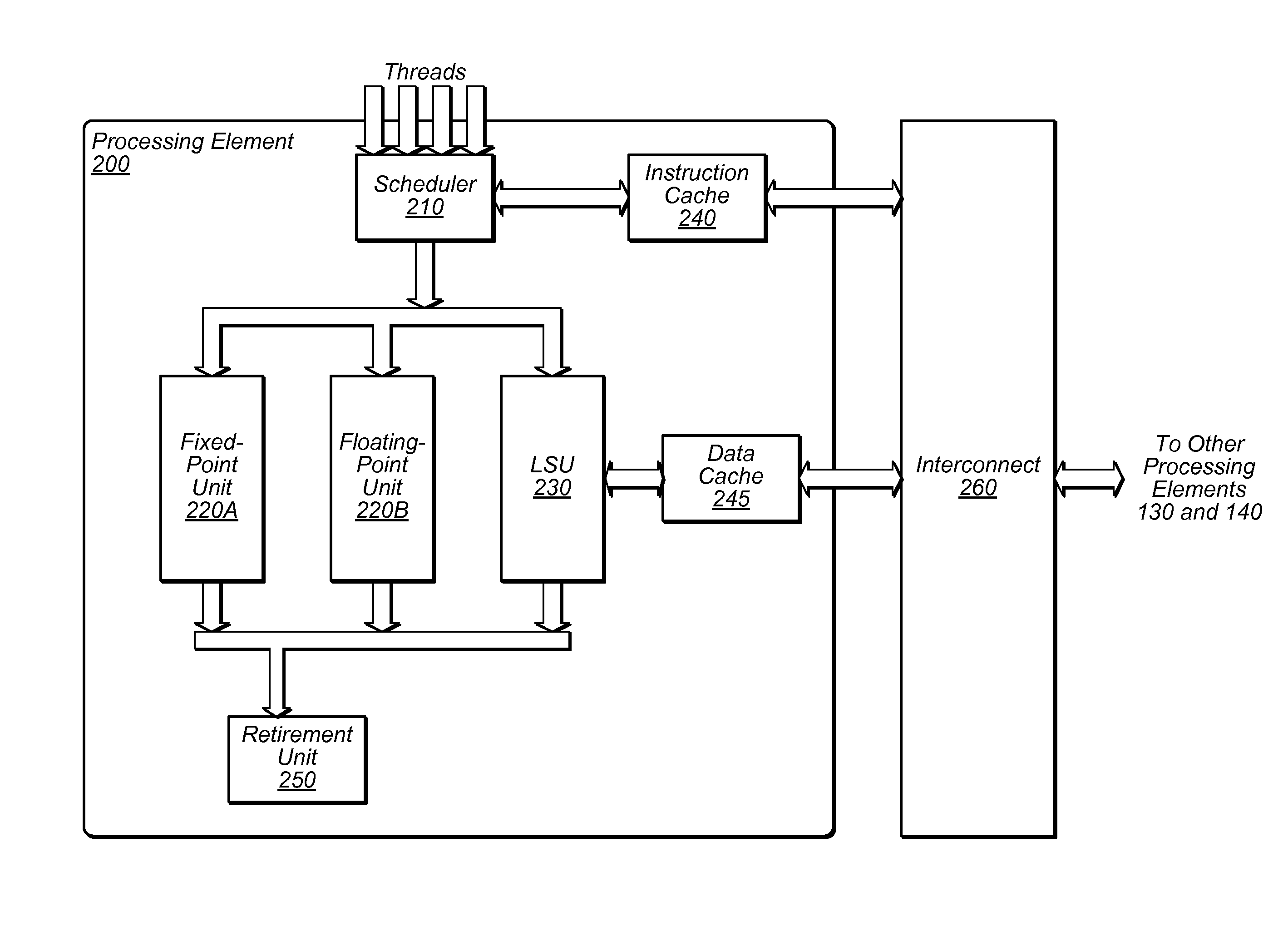
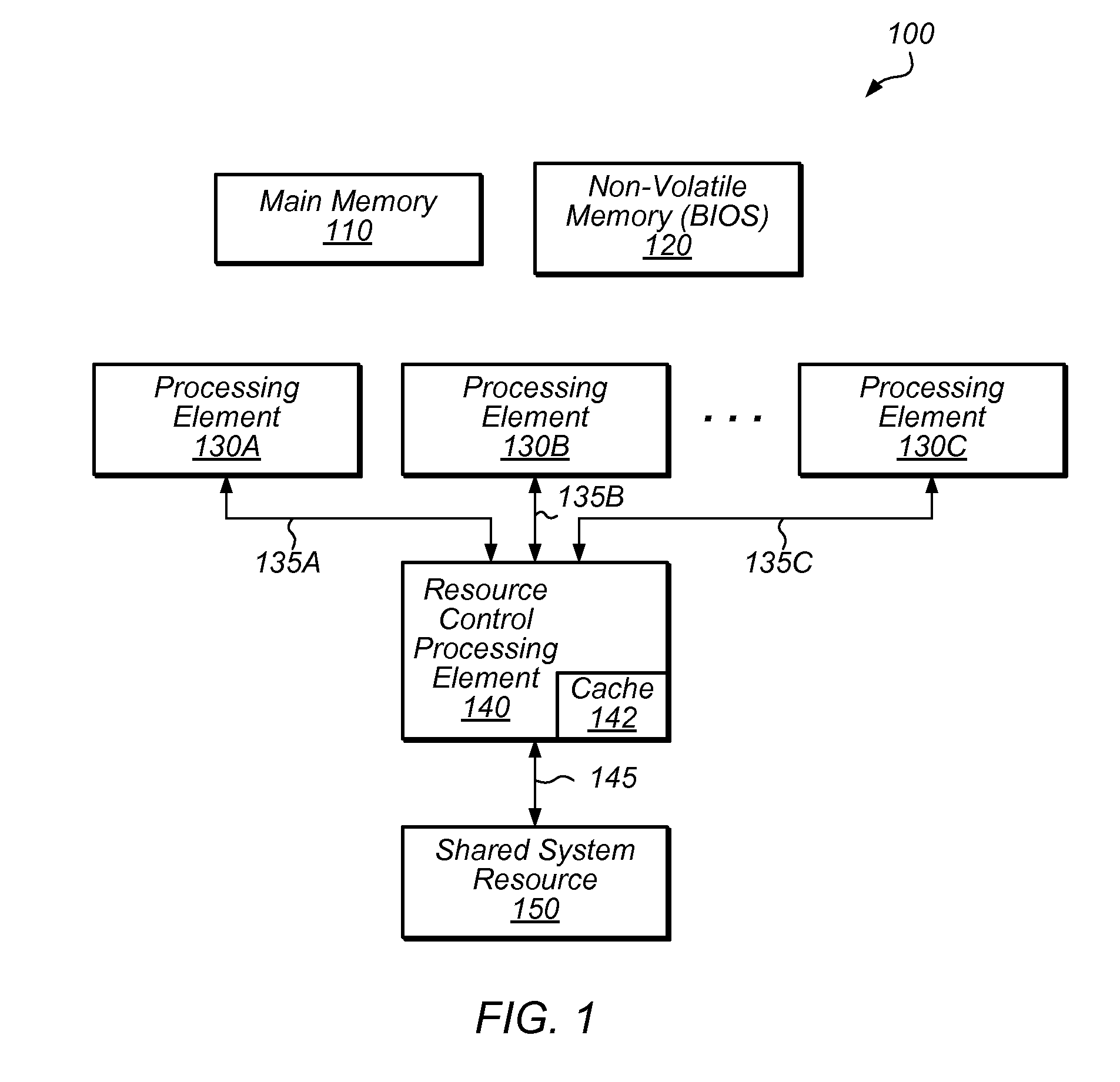
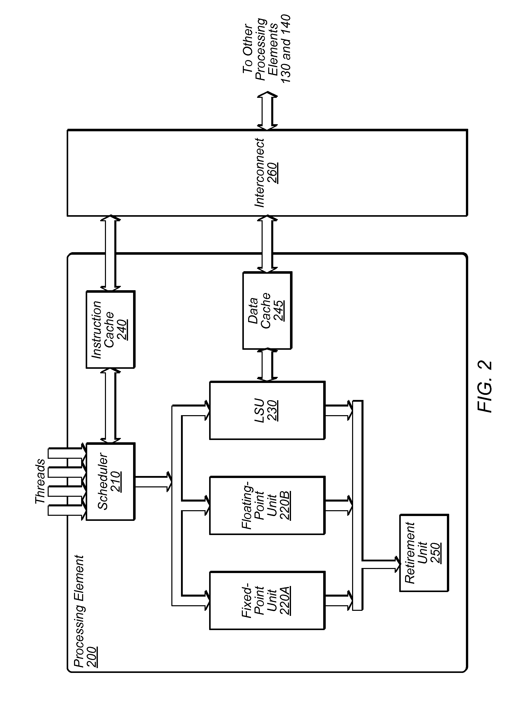
[0015]In one embodiment, an apparatus is disclosed. The apparatus includes a processing element configured to communicate with a resource control processing element and a shared hardware resource during a prememory state. During the prememory state, the processing element is configured to send a request to the resource control processing element to access the shared hardware resource, and to receive a response to the request indicating that the processing element has been granted access to the shared hardware resource.

Problems solved by technology

When a computer system boots up, however, system memory (e.g., “main memory”) is not immediately accessible to system processors because it has not yet been initialized.
In this “pre-memory” environment, resource contention can cause starvation.
For example, if access to a resource is obtained on a first-come, first-serve basis, certain processors may be more likely to gain access to a resource while others may rarely or never gain access in a timely manner, resulting in slower boot times. Slow boot times may also be exacerbated by the fact that the resource may only be available via a (relatively) slow bus.
Furthermore, access to the resource may be serialized, resulting in an increase in execution time.
Resources may also be inefficiently utilized since they are accessed only whenever processors require data and remain idle when processors are executing other tasks.
In some instances, this can result in a further delay of overall processor execution time, again leading to slower boot times.

Method used


Image

  • Pre-memory resource contention resolution
  • Pre-memory resource contention resolution
  • Pre-memory resource contention resolution

Examples


Embodiment Construction

[0025]This specification includes references to “one embodiment” or “an embodiment.” The appearances of the phrases “in one embodiment” or “in an embodiment” do not necessarily refer to the same embodiment. Particular features, structures, or characteristics may be combined in any suitable manner consistent with this disclosure.

[0026]Terminology. The following paragraphs provide definitions and / or context for terms found in this disclosure (including the appended claims):

[0027]“Comprising.” This term is open-ended. As used in the appended claims, this term does not foreclose additional structure or steps. Consider a claim that recites: “An apparatus comprising one or more processor units . . . .” Such a claim does not foreclose the apparatus from including additional components (e.g., a network interface unit, graphics circuitry, etc.).

[0028]“Configured To.” Various units, circuits, or other components may be described or claimed as “configured to” perform a task or tasks. In such c...


PUM


Abstract

Techniques are disclosed relating to resource contention resolution in a pre-memory environment. Prior to system memory being accessible, a resource control processing element controls access to a hardware resource by a plurality of processing elements by granting received requests from the processing elements for access to the resource. The resource control processing element may prioritize requests based on a determined amount of utilization of the hardware resource by individual ones of the processing elements. In one embodiment, processing elements request for information from a bus controller (e.g., an SMBus controller) that is usable to initialize system memory. The resource control processing element may respond to the requests by retrieving the requested information from the controller and providing that information to the processing element or by retrieving the requested information from a cache and providing that information to the processing element.

Description

BACKGROUND[0001]1. Technical Field[0002]This disclosure relates generally to resource allocation in a computer system and, more specifically, to resolving resource contention in a computer system operating in a pre-memory state.[0003]2. Description of the Related Art[0004]Resource contention in a computer system can occur when multiple processors try to concurrently access a shared resource. Traditionally, resource contention is managed using data structures such as locks or semaphores that are stored in system memory.[0005]When a computer system boots up, however, system memory (e.g., “main memory”) is not immediately accessible to system processors because it has not yet been initialized. In this “pre-memory” environment, resource contention can cause starvation. For example, if access to a resource is obtained on a first-come, first-serve basis, certain processors may be more likely to gain access to a resource while others may rarely or never gain access in a timely manner, resu...

Claims


Application Information

Patent Timeline
Patent Type & Authority Applications(United States)
IPC IPC(8): G06F13/362
CPCG06F9/52G06F9/4401
Inventor HOUSTY, OSWIN E.
Owner ADVANCED MICRO DEVICES INC
Learn More