
Method for dynamic suppression of surrounding acoustic noise when listening to electrical inputs

a technology of electrical input and surrounding acoustic noise, applied in the field of dynamic suppression of surrounding acoustic noise when listening to electrical input, can solve the problems of user still having problems, interference with the perceived audio quality and speech interpretation, and the signal to noise ratio (s/n) of the combined signal may be too low to allow him/her to understand the electrical input signal, etc., to achieve the effect of improving listening comfor

Active Publication Date: 2011-06-09
OTICON
View PDF28 Cites 119 Cited by
  • Summary
  • Abstract
  • Description
  • Claims
  • Application Information

AI Technical Summary

Benefits of technology

An advantage of the invention is that it provides improved listening comfort to a user in different acoustic environments.

Problems solved by technology

In the latter situation the surrounding audio environment can interfere with the perceived audio quality and speech interpretation, if e.g. the listener is in a noisy environment.
However, the user still has problems, if he / she is in a noisy environment and needs to address persons in their proximity, while receiving a direct electric input.
If a wearer leaves the microphone(s) off, he / she will not be able to communicate with persons in the near proximity, and if he / she leaves the microphone(s) on, the signal to noise ratio (S / N) of the combined signal may be too low to allow him / her to understand the electrical input signal.

Method used


Image

  • Method for dynamic suppression of surrounding acoustic noise when listening to electrical inputs
  • Method for dynamic suppression of surrounding acoustic noise when listening to electrical inputs
  • Method for dynamic suppression of surrounding acoustic noise when listening to electrical inputs

Examples


Embodiment Construction

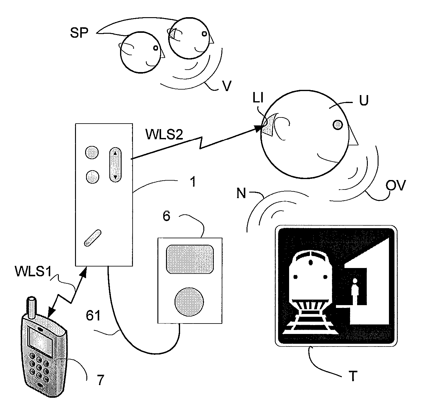
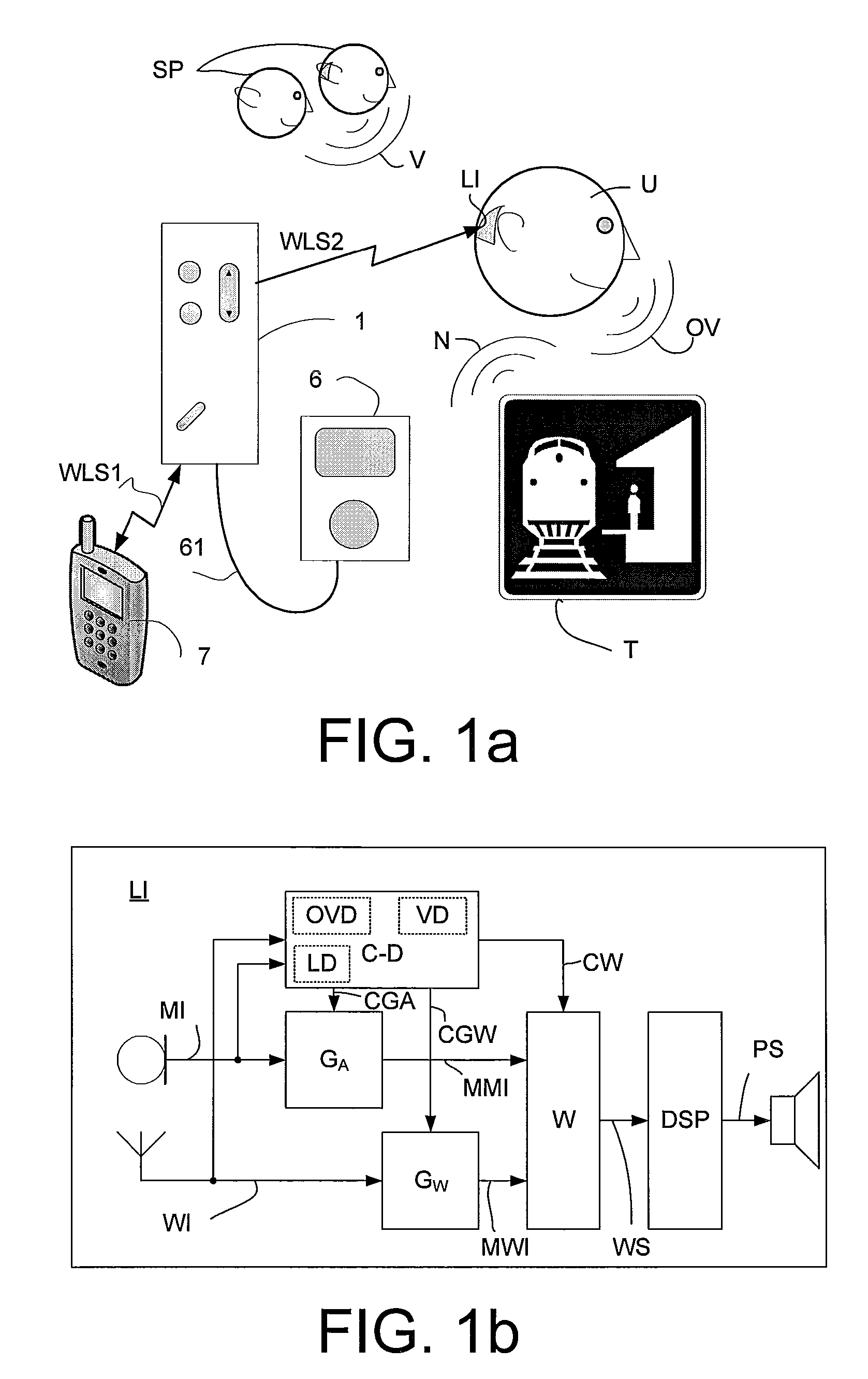
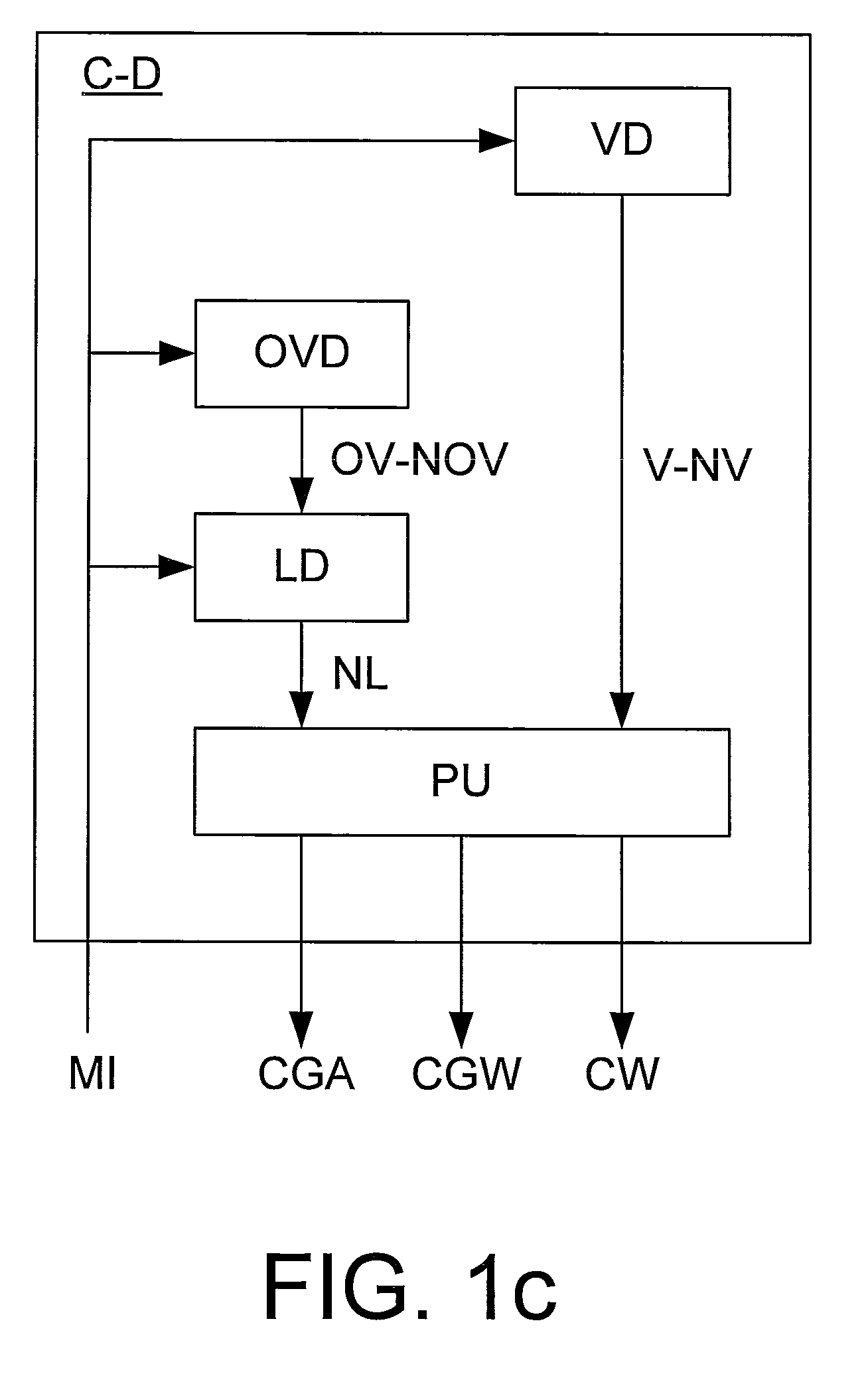
FIG. 1a shows a listening scenario comprising a specific acoustic environment for a user wearing a listening instrument. FIG. 1a shows a user U wearing a listening instrument LI adapted for being worn by the user. A listening instrument is typically adapted to be worn at or in an ear of a user. In an embodiment, the listening instrument comprises a hearing instrument being adapted or fitted to a particular user (e.g. to compensate for a hearing impairment). The listening instrument LI is adapted to receive an audio signal from an audio gateway 1 as a direct electric input (WI in FIG. 1b), here a wireless input received via a wireless link WLS2. The audio gateway 1 is adapted for receiving a number of audio signals from a number of audio sources, here cellular phone 7 via wireless link WLS1, and audio entertainment device (e.g. music player) 6 via wired connection 61 and for transmitting a selected one of the audio signals to the listening instrument LI via wireless link WLS2. The li...


PUM


Abstract

A listening instrument includes a) a microphone unit for picking up an input sound from the current acoustic environment of the user and converting it to an electric microphone signal; b) a microphone gain unit for applying a specific microphone gain to the microphone signal and providing a modified microphone signal; c) a direct electric input signal representing an audio signal; d) a direct gain unit for applying a specific direct gain to the direct electric input signal and providing a modified direct electric input signal; e) a detector unit for classifying the current acoustic environment and providing one or more classification parameters; f) a control unit for controlling the specific microphone gain applied to the electric microphone signal and / or the specific direct gain applied to the direct electric input signal based on the one or more classification parameters.

Description

TECHNICAL FIELDThe present application relates to improving a signal to noise ratio in listening devices. The application relates specifically to a listening instrument adapted for being worn by a user and for receiving an acoustic input as well as an electric input representing an audio signal.The application furthermore relates to the use of a listening instrument and to a method of operating a listening instrument. The application further relates to a data processing system comprising a processor and program code means for causing the processor to perform at least some of the steps of the method and to a computer readable medium storing the program code means.The disclosure may e.g. be useful in applications such as hearing aids, headsets, active ear protection devices, head phones, etc.BACKGROUND ARTThe following account of the prior art relates to one of the areas of application of the present application, hearing aids.Originally, wireless or wired electrical inputs to hearing ...

Claims


Application Information

Patent Timeline
Patent Type & Authority Applications(United States)
IPC IPC(8): G10L15/00
CPCH04R25/356H04R25/43H04R2460/01H04R2225/41H04R2225/43H04R25/554
Inventor RASMUSSEN, CRILLES BAKTHOMSEN, ANDERS HOJSGAARD
Owner OTICON
Learn More