
Load supporting panel having impact absorbing structure

a technology of load support and impact absorption, which is applied in the direction of pavements, applications, roads, etc., can solve the problems of limited surface design, and achieve the effects of reducing the volume of material, and reducing the impact load

Active Publication Date: 2011-06-09
BROCK USA
View PDF54 Cites 29 Cited by
  • Summary
  • Abstract
  • Description
  • Claims
  • Application Information

AI Technical Summary

Benefits of technology

[0005]This invention also relates to an impact absorption panel having a top side and a bottom side where the bottom side has a plurality of projections disposed across at least a portion of the bottom surface. The projections have a first spring rate characteristic and a second spring rate characteristic. The first spring rate characteristic provides for more deflection under load than the second spring rate characteristic.
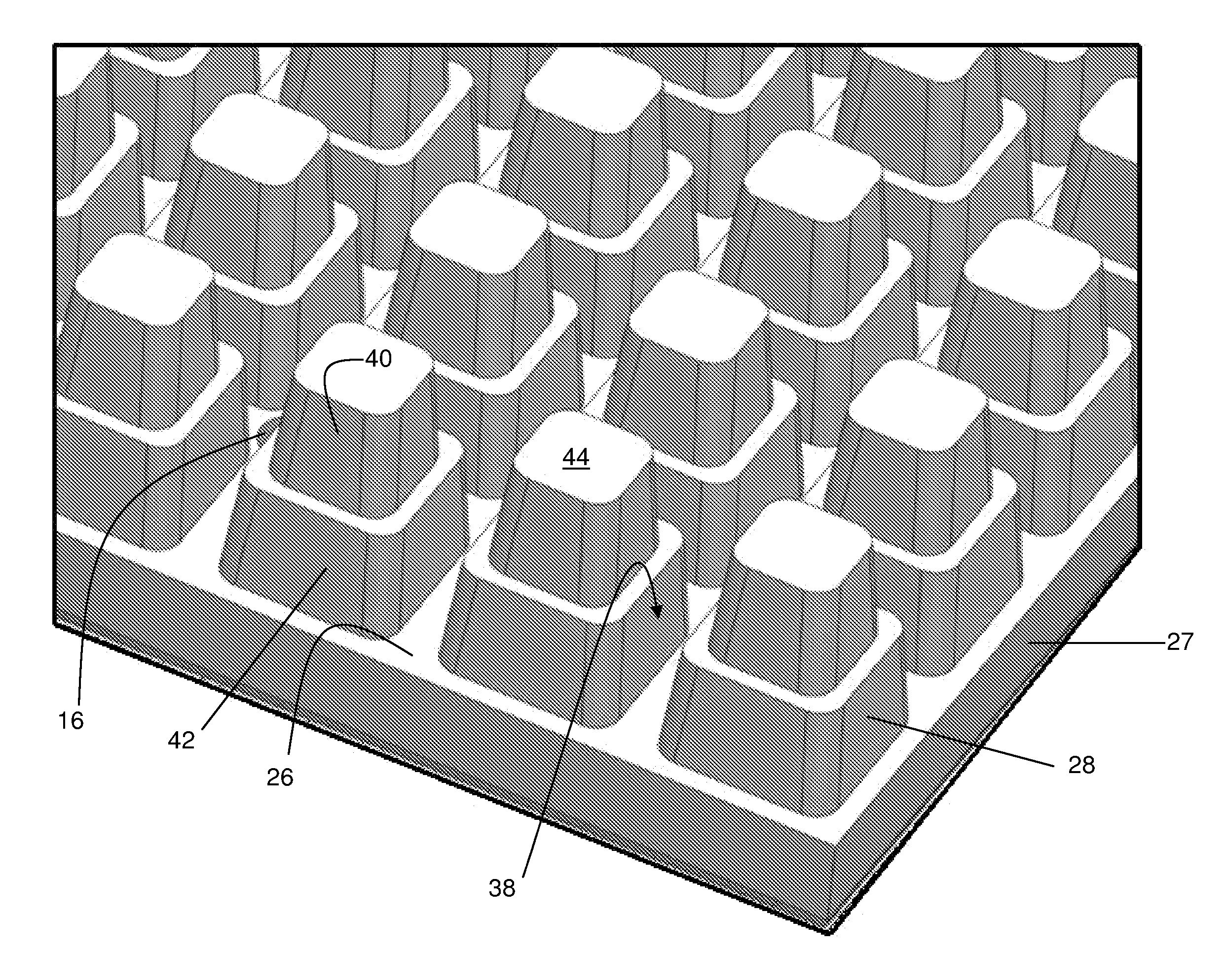
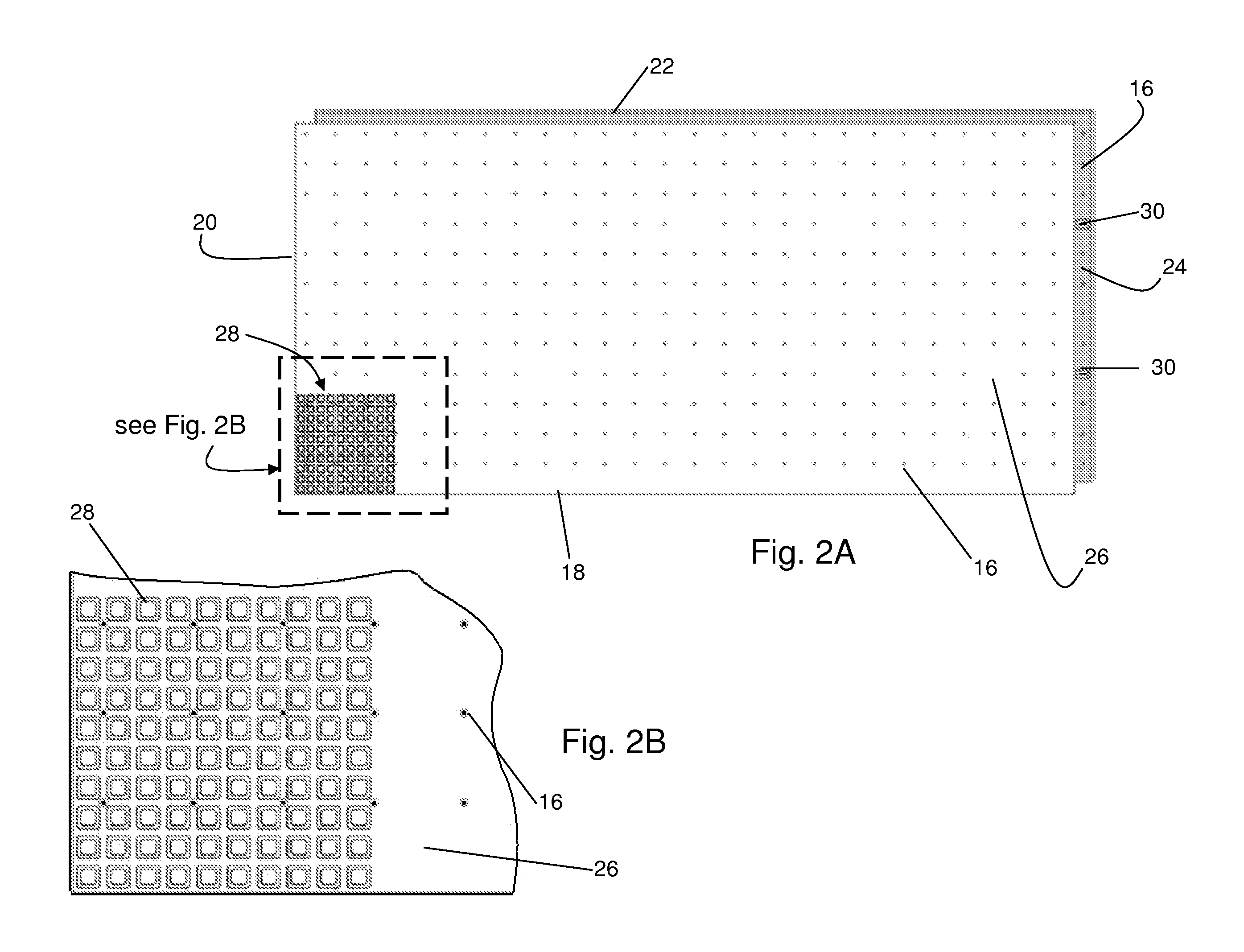
[0006]In one embodiment, an impact absorption panel comprises a top surface and a bottom surface. The top surface has a three dimensional textured surface and a plurality of intersecting drainage channels. The bottom surface is spaced apart from the top surface and defines a panel section therebetween. A plurality of projections is disposed across at least a portion of the bottom surface. The projections have a first stage that defines a first spring rate characteristic and a second stage defining a second spring rate characteristic. The first spring rate characteristic provides for more deflection under load than the second spring rate characteristic. The plurality of projections also cooperate during deflection under load such that the adjacent projections provide a load absorption gradient over a larger area than the area directly loaded. In another embodiment, the first stage has a smaller volume of material than the second stage. Additionally, the adjacent projections define a bottom surface channel to form a plurality of intersecting bottom surface channels and a plurality of drain holes connect the top surface drainage channels with the plurality of bottom surface channels at the drainage channel intersections.
[0007]In another embodiment, an impact absorption panel includes a top surface and a bottom surface that define a panel section. A plurality of projections are supported from the bottom surface, where the projections include a first stage having a first spring rate and a second stage having a second spring rate. The first stage is configured to collapse initially when subjected to an impact load, the second stage is configured to provide greater resistance to the impact load than the first stage, and the panel section is configured to provide greater resistance to the impact load than the first and second stages. The first stage is also configured to compress and telescopically deflect, at least partially, into the second stage. A portion of the bottom surface is generally coplanar with the truncated ends of adjacent projections such that the coplanar bottom surface portion is configured to provide a substantial resistance to deflection under load compared with the first and second stages. This coplanar configuration of the bottom surface provides a structural panel section having a thickness that is generally equal to the thickness of the panel section plus the length of the projections.

Problems solved by technology

These surface designs, however, are limited by the ability of the materials to spread the impact load over a large area.

Method used


Image

  • Load supporting panel having impact absorbing structure
  • Load supporting panel having impact absorbing structure
  • Load supporting panel having impact absorbing structure

Examples


Embodiment Construction

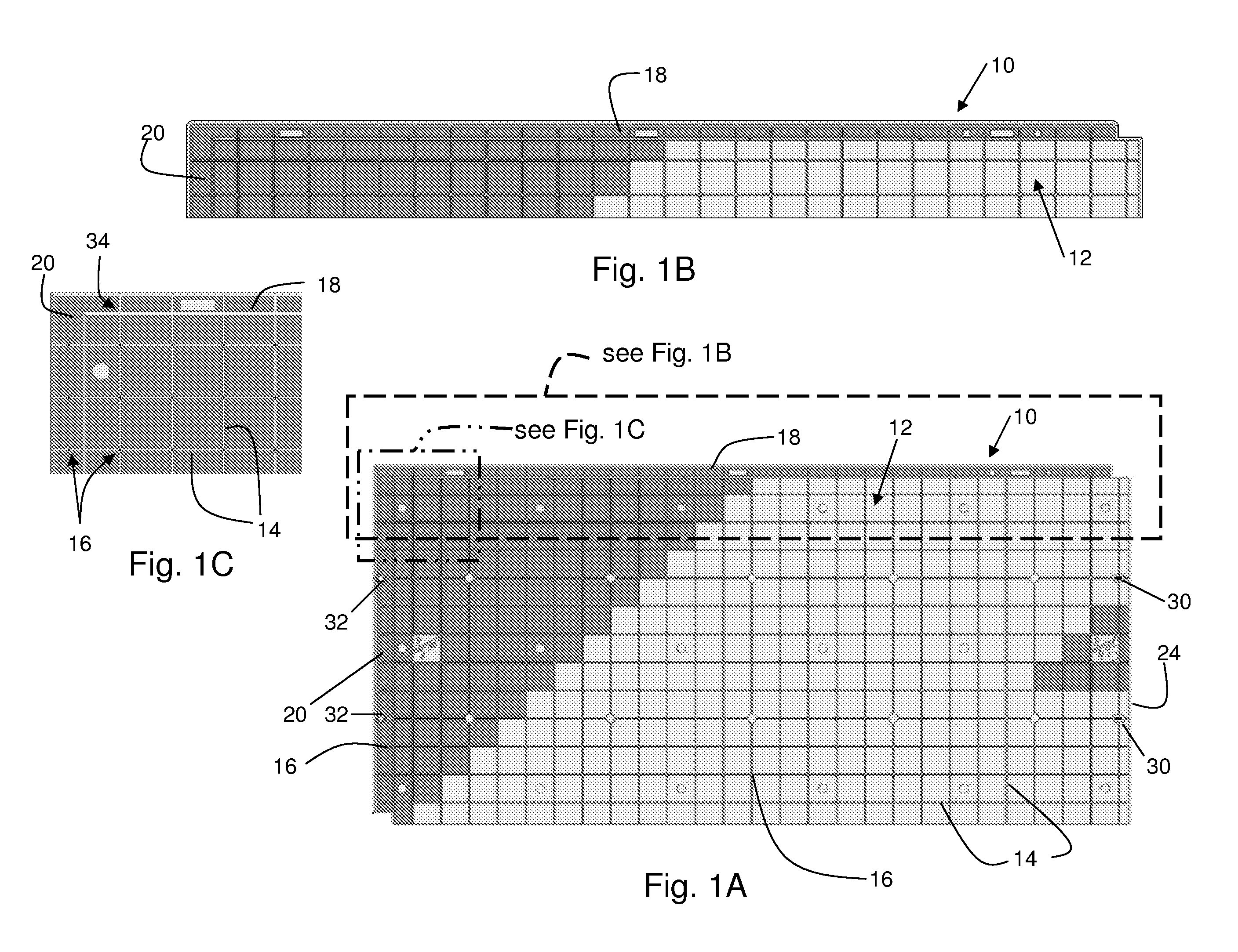
[0024]Referring now to the drawings, there is illustrated in FIGS. 1A, 1B, and 1C a load supporting panel having an impact absorbing structure configured to underlie a playground area. The various embodiments of the impact absorbing panel described herein may also be used in indoor and outdoor impact environments other than playgrounds and with other types of equipment such as, for example, wrestling mats, gymnastic floor pads, carpeting, paving elements, loose infill material, and other covering materials. In certain embodiments, the panel is described as a single panel and is also configured to cooperate with other similar panels to form a base or impact absorbing panel system that is structured as an assemblage of panels. The panel, shown generally at 10, has a top surface 12 that is illustrated having a grid of drainage channels 14. Though shown as a grid of intersecting drainage channels 14, the drainage channels may be provided in a non-intersecting orientation, such as genera...


PUM

PropertyMeasurementUnit
heightaaaaaaaaaa
heightaaaaaaaaaa
heightaaaaaaaaaa

Abstract

An impact absorption panel is adapted for playground use and comprises a panel section and a plurality of projections. The panel section is defined by a top surface and a bottom surface. The plurality of projections extend from the bottom surface of the panel section. The plurality of projections have a first stage and a second stage. The first stage is configured to collapse initially when subjected to an impact load. The second stage is configured to provide greater resistance to the impact load than the first stage. The panel section is configured to provide greater resistance to the impact load than the first and second stages. The first stage can also be distinguished from the second stage by virtue of having a comparatively smaller volume.

Description

CROSS-REFERENCE TO RELATED APPLICATIONS[0001]This application is a continuation-in-part patent application of U.S. patent application Ser. No. 12 / 009,835, filed Jan. 22, 2008, and U.S. patent application Ser. No. 12 / 830,902, filed Jul. 6, 2010, the disclosure of both applications are incorporated herein by reference. This application also claims the benefit of U.S. Provisional Application No. 61 / 303,350, filed Feb. 11, 2010, the disclosure of which is incorporated herein by reference.BACKGROUND OF THE INVENTION[0002]This invention relates in general to impact absorbing underlayment panels. In particular, this invention relates to underlayment panels having deformable elements that compress in a plurality of stages such that a load absorbing gradient is provided in response to an applied force.[0003]Surfaces such as playgrounds and athletic mats, for example, are scrutinized for their effect on impact forces that cause related injuries to users. Attempts have been made to minimize th...

Claims


Application Information

Patent Timeline
Patent Type & Authority Applications(United States)
IPC IPC(8): E01C13/08B32B3/24B32B3/00B32B3/30
CPCE01C11/225E01C13/045E01C2201/14E01C13/04Y10T428/192E04F15/225E01C3/06Y10T428/24273E04B5/48E04F15/02194E04F15/102E04F15/105E04F15/107E01C11/02E01C2201/10E01C2201/12E01C2201/207E01C5/001E01C5/003E01C5/18E01C5/20E01C5/226E01C9/00E01C13/02
Inventor SAWYER, STEVEN LEE
Owner BROCK USA
Learn More