Image forming apparatus and image processing method
a technology of image processing and forming apparatus, which is applied in the direction of digitally marking record carriers, visual presentation using printers, instruments, etc., can solve the problems of uneven density of edges in portions, etc., to prevent the occurrence of deterioration in picture quality
- Summary
- Abstract
- Description
- Claims
- Application Information
AI Technical Summary
Benefits of technology
Problems solved by technology
Method used
Image
Examples
first embodiment
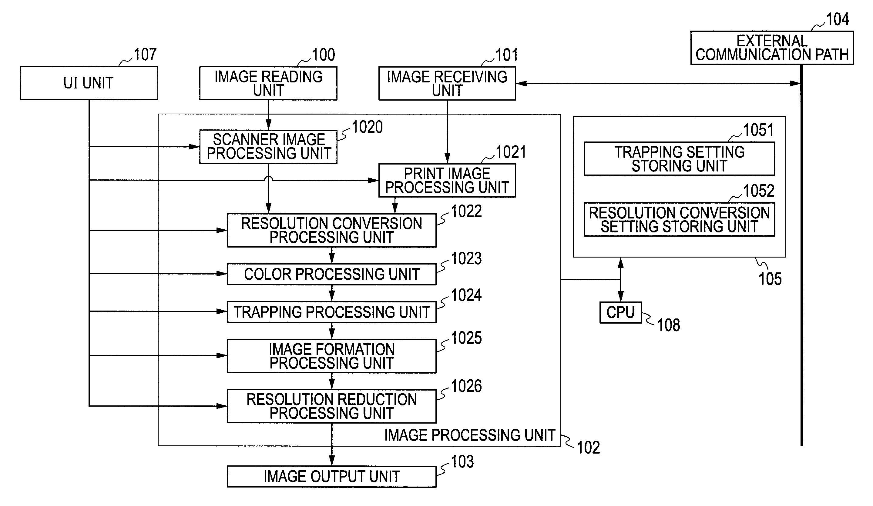
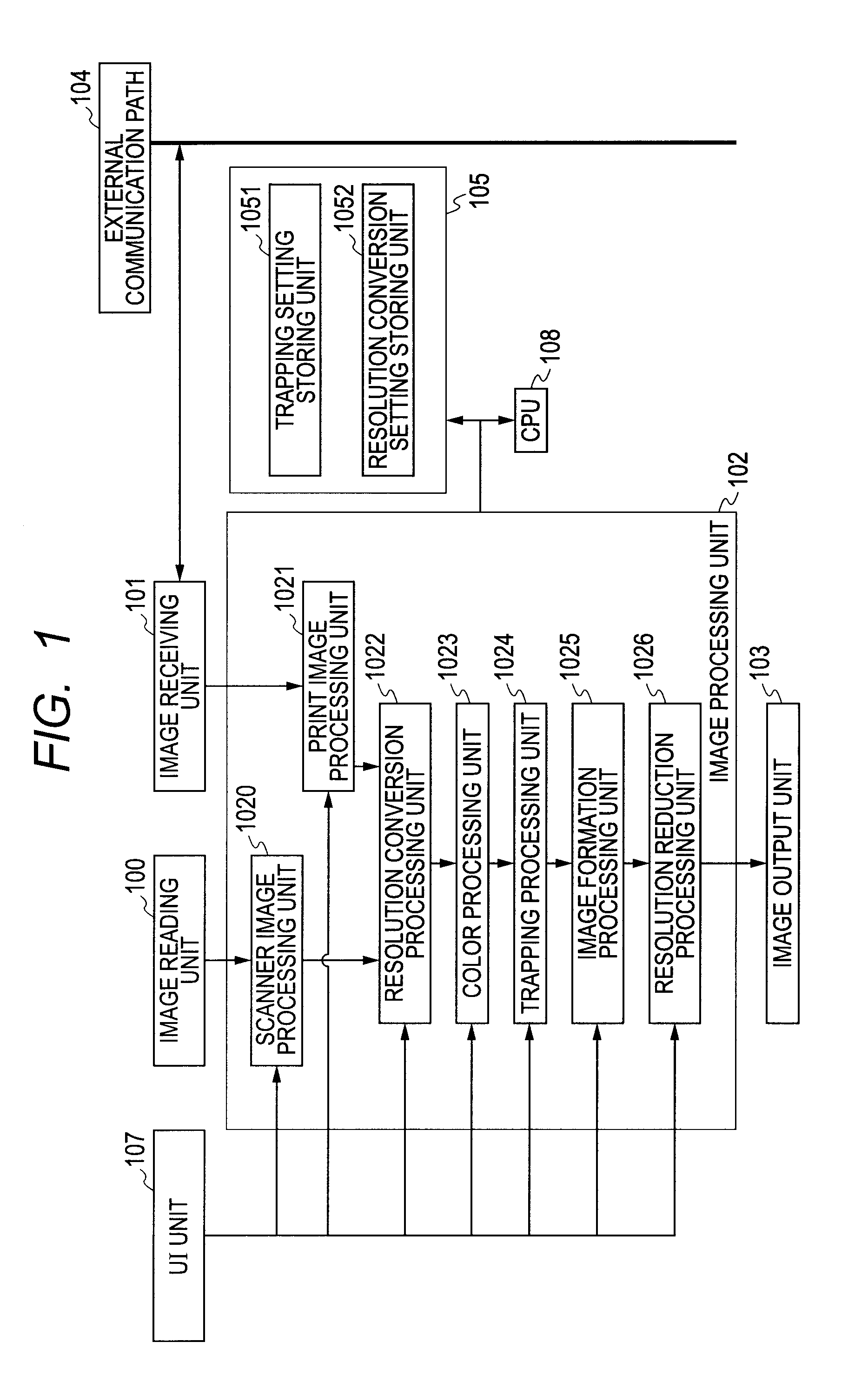
[0019]Details of an image process in an image forming apparatus according to an embodiment of the invention will be described hereinbelow with reference to the drawings. FIG. 1 is a schematic block diagram of the image forming apparatus according to the first embodiment of the invention. Although a digital multifunction apparatus or the like is presumed as an image forming apparatus in the embodiment hereinbelow, not only a copying apparatus but also other printing devices such as a color printer and the like can be also used. First, a structure of the image forming apparatus according to the embodiment will be described. As illustrated in FIG. 1, an image forming apparatus 800 has an image reading unit 100, an image receiving unit 101, a UI unit 107, an image processing unit 102 for executing various kinds of image processes, a storing unit 105, a CPU 106, and an image output unit 103. The image forming apparatus 800 can be also connected to a server for managing image data, a pers...
second embodiment
[0051]Subsequently, a second embodiment will be described with respect to a system in which even in the case where the user does not make the exclusive control by using the detail setting, the exclusive control of the trapping process and the resolution converting process is automatically made. The construction and operation of the first embodiment other than the procedure described in FIG. 4 are also common to those in the second embodiment. The second embodiment differs from the first embodiment with respect to the operations by the trapping processing unit and the resolution conversion processing unit and its procedure is illustrated in FIGS. 5A and 5B.
[0052]The resolution converting process will be described with reference to FIG. 5A. This procedure shows details in the embodiment of step S304 in FIG. 3A. First, the resolution conversion processing unit is executed with respect to the target pixel in a manner similar to the first embodiment (S501). After that, a weight or averag...
third embodiment
[0055]Subsequently, in the third embodiment, an example in which when the trapping and the weight resolution converting process are selected by the user, the weight resolution conversion is executed or the converting mode is switched to the maximum resolution conversion or the simple resolution conversion according to the density of the reference pixel will be described by using FIG. 10.
[0056]At the time of the resolution process, whether or not the attribute of the target pixel is the same as the attribute adapted to perform the weight resolution conversion is discriminated by the user from 712 in FIG. 7B (S1001). If YES here, whether or not the target pixel which is set from 613 in FIG. 6B has the density adapted to perform the trapping is discriminated (S1002). If YES here, whether or not the reference pixel which is set from 614 has the density adapted to perform the trapping is discriminated (S1003). If NO here, the weight conversion is executed (S1004).
[0057]In the processing ...
PUM
 Abstract
Description
Claims
Application Information
 - R&D
- Intellectual Property
- Life Sciences
- Materials
- Tech Scout
- Unparalleled Data Quality
- Higher Quality Content
- 60% Fewer Hallucinations
Browse by: Latest US Patents, China's latest patents, Technical Efficacy Thesaurus, Application Domain, Technology Topic, Popular Technical Reports.
© 2025 PatSnap. All rights reserved.Legal|Privacy policy|Modern Slavery Act Transparency Statement|Sitemap|About US| Contact US: help@patsnap.com


