
Control device for electric motor drive device

a technology of control device and electric motor, which is applied in the direction of electric generator control, dynamo-electric converter control, dynamo-electric gear control, etc., can solve the problems of unnecessarily short period of current control process and voltage control process, and problems that may become significant, so as to reduce the possibility of an overshoot phenomenon and reduce the capability of current detection value.

Inactive Publication Date: 2011-06-02
AISIN AW CO LTD
View PDF7 Cites 13 Cited by
  • Summary
  • Abstract
  • Description
  • Claims
  • Application Information

AI Technical Summary

Benefits of technology

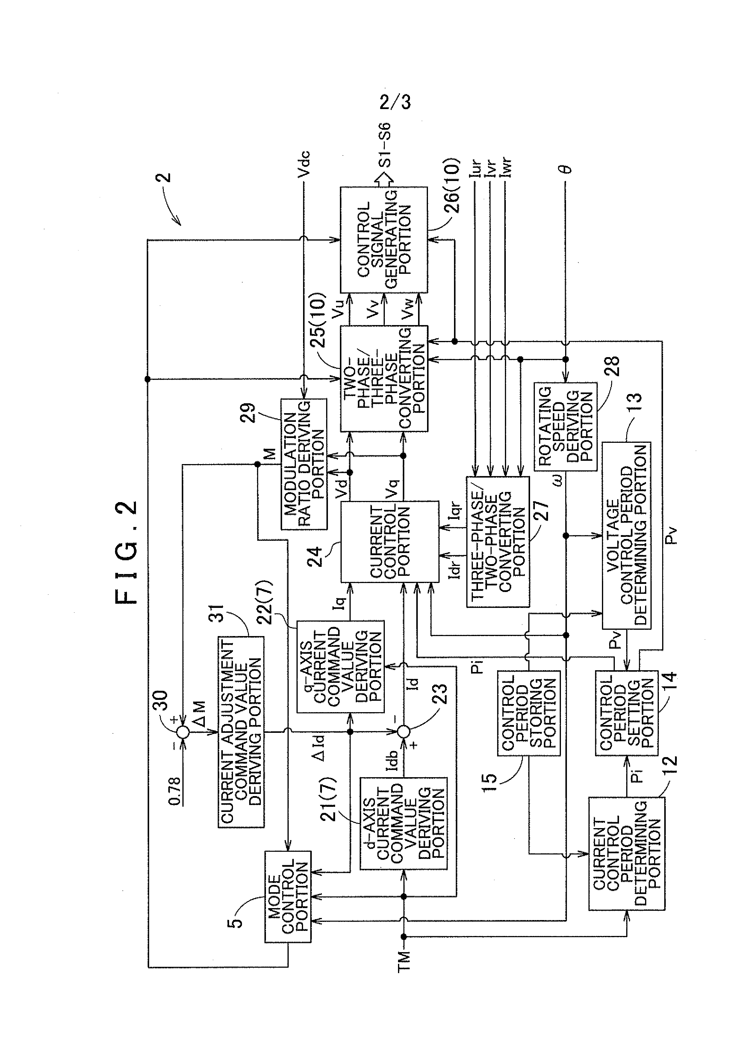
[0008]According to the first aspect above, the current control period is set to a larger value as the target torque of the AC electric motor decreases. This enables the current control period to be set appropriately according to response characteristics of the AC electric motor which degrade as the target torque decreases. This can reduce the possibility that the voltage command value may be updated (the current control process may be performed) with such a short period that the AC electric motor cannot follow appropriately.
[0020]With this structure, the proportional control gain and the integral control gain can be appropriately set while reducing the possibility of an overshoot phenomenon and a decrease in capability of the current detection value to follow the current command value, when the current control period is changed.

Problems solved by technology

However, in the structure in which the current control period and the voltage control period are set to fixed value as described above, the current control process and the voltage control process may possibly be performed with an unnecessarily short period if the AC electric motor is operating at an operating point that is significantly different from the limit operating point.
This problem may become significant if the control device is a device for controlling an AC electric motor that is mounted as a driving force source on electric vehicles, hybrid vehicles, or the like.

Method used


Image

  • Control device for electric motor drive device
  • Control device for electric motor drive device
  • Control device for electric motor drive device

Examples


Embodiment Construction

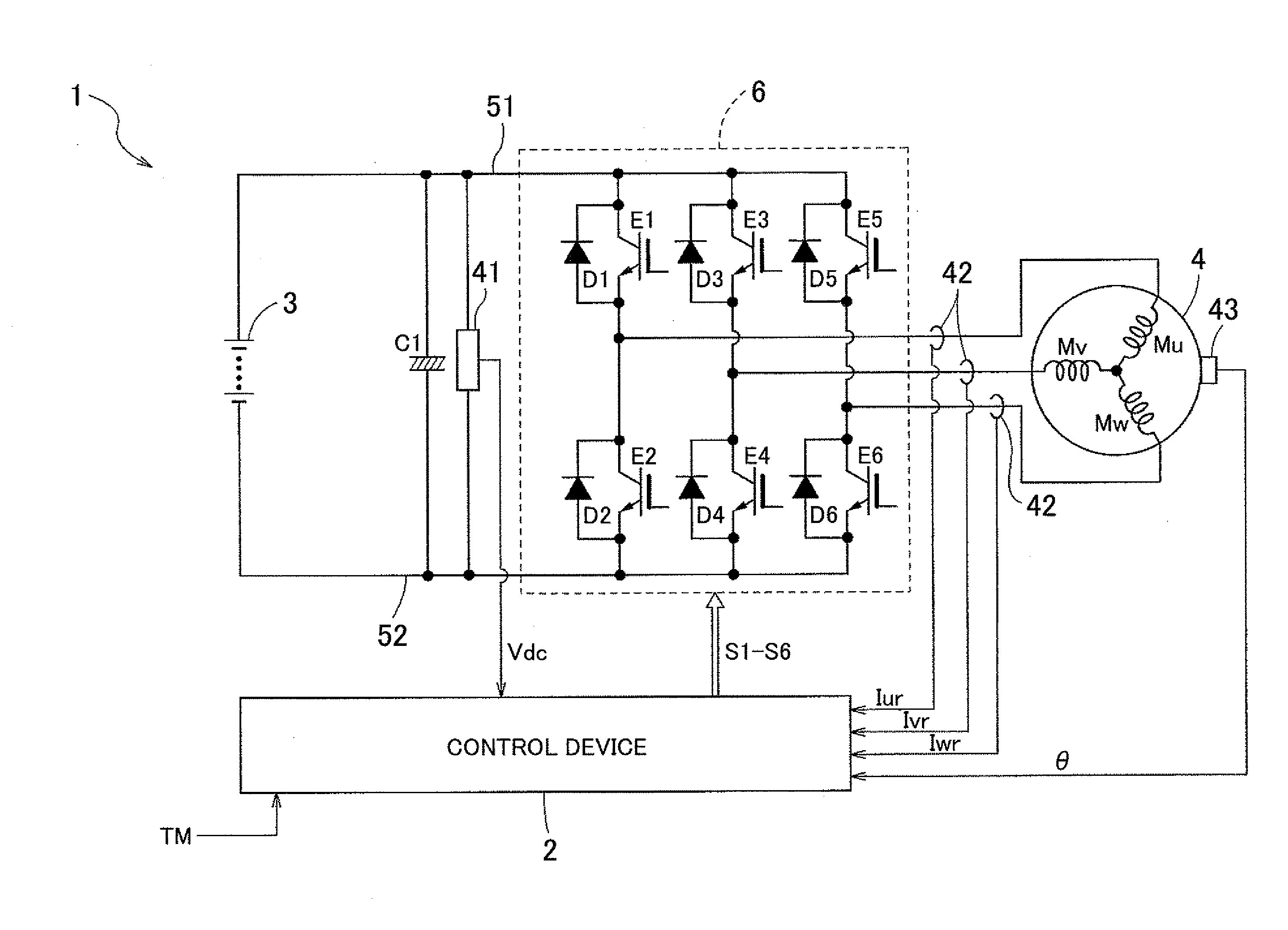
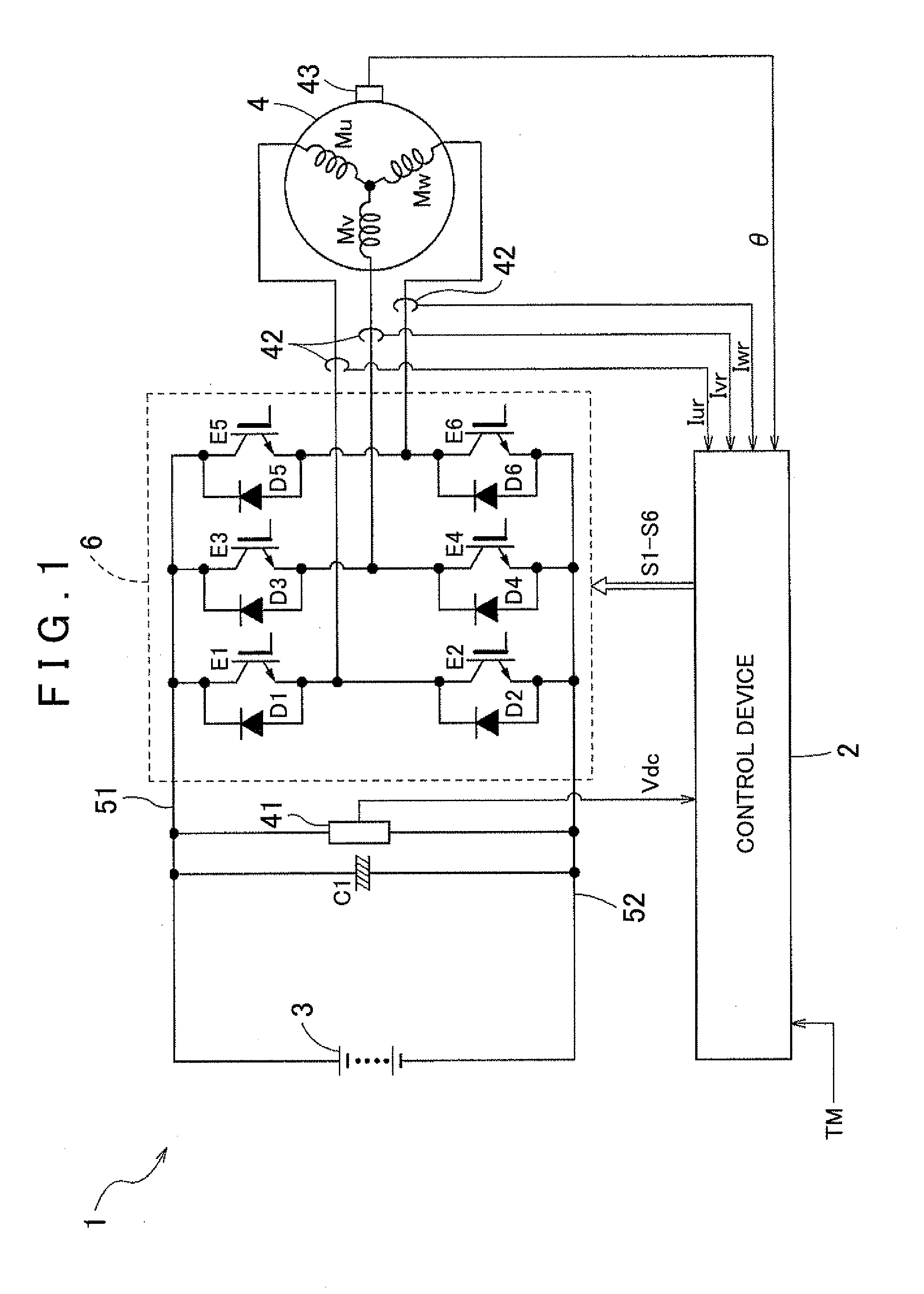
[0025]An embodiment of a control device for an electric motor drive device according to the present invention will be described below with reference to the accompanying drawings. As shown in FIG. 1, the present embodiment will be described with respect to an example in which an electric motor drive device 1 is structured as a device for driving an interior permanent magnet synchronous electric motor 4 (IPMSM; hereinafter simply referred to as the “electric motor 4”) as an AC electric motor that is operated by a three-phase alternating current. In the present embodiment, a control device 2 controls the electric motor control device 1 to perform current feedback control of the electric motor 4 by using a vector control method. More specifically, as shown in FIG. 2, the control device 2 includes a current control portion 24 for performing a current control process in every current control period Pi, and a voltage control portion 10 for performing a voltage control process in every volt...


PUM


Abstract

A control device that controls an electric motor drive device is configured with a current control portion that determines a voltage command value, a voltage control portion that generates a switching control signal, and a current control period determining portion. The control device is also configured with a voltage control period determining portion that determines a voltage control period, and a control period setting portion. In the control device, the current control period determining portion determines, according to a target torque, the current control period as a value that increases continuously or stepwise as the target torque decreases. Furthermore, the voltage control period determining portion determines, according to a rotating speed, the voltage control period as a value that increases continuously or stepwise as the rotating speed decreases.

Description

INCORPORATION BY REFERENCE[0001]The disclosure of Japanese Patent Application No. 2009-272840 filed on Nov. 30, 2009 including the specification, drawings and abstract is incorporated herein by reference in its entirety.BACKGROUND OF THE INVENTION[0002]The present invention relates to control devices for controlling an electric motor drive device having an inverter that converts a direct current (DC) voltage to an alternating current (AC) voltage to supply the AC voltage to an AC electric motor.DESCRIPTION OF THE RELATED ART[0003]A control device is known that controls an electric motor drive device having an inverter that converts a DC voltage from a DC power source to an AC voltage to supply the AC voltage to an AC electric motor, and performs current feedback control of the AC electric motor. Such a control device for an electric motor drive device repeatedly performs both a current control process and a voltage control process in every predetermined period. The current control p...

Claims


Application Information

Patent Timeline
IPC IPC(8): H02P27/06H02P21/00H02P21/22H02P23/07H02P27/04H02P27/08
CPCB60L15/20B60L2210/20H02P6/08H02P21/0085Y02T10/7275H02P21/06Y02T10/643Y02T10/644Y02T10/725H02P21/0089Y02T10/64Y02T10/72
Inventor SHIMADA, ARINORISAHA, SUBRATAIWATSUKI, KEN
Owner AISIN AW CO LTD
Learn More