Camera module with autofocus function

Active Publication Date: 2011-05-19
MCNEX
View PDF8 Cites 11 Cited by
  • Summary
  • Abstract
  • Description
  • Claims
  • Application Information

AI Technical Summary

Benefits of technology

[0012]The present invention is directed to a camera module with an autofocus function in which the wiring terminals of the coil section can be easily connected to the connection terminals of the PCB regardless of the position of the wiring terminals of the coil section when the lens section rotates with respect to the PCB for precise focus adjustment.

Problems solved by technology

However, since the autofocus adjusting apparatus uses the gear, it is difficult to precisely adjust the focus.
Further, due to the space occupied by the motor and the gear, there is a limit to reducing the size of the terminal.
However, in this case, the wiring terminals may unnecessarily remain lengthy after soldered to the connection terminals, leading to the problem on how to deal with the wiring terminals.

Method used


Image

  • Camera module with autofocus function
  • Camera module with autofocus function
  • Camera module with autofocus function

Examples


Embodiment Construction

[0039]The invention is described more fully hereinafter with reference to the accompanying drawings, in which exemplary embodiments of the invention are shown. This invention may, however, be embodied in many different forms and should not be construed as limited to the exemplary embodiments set forth herein. Rather, these exemplary embodiments are provided so that this disclosure is thorough, and will fully convey the scope of the invention to those skilled in the art. In the drawings, the size and relative sizes of layers and regions may be exaggerated for clarity. Like reference numerals in the drawings denote like elements.

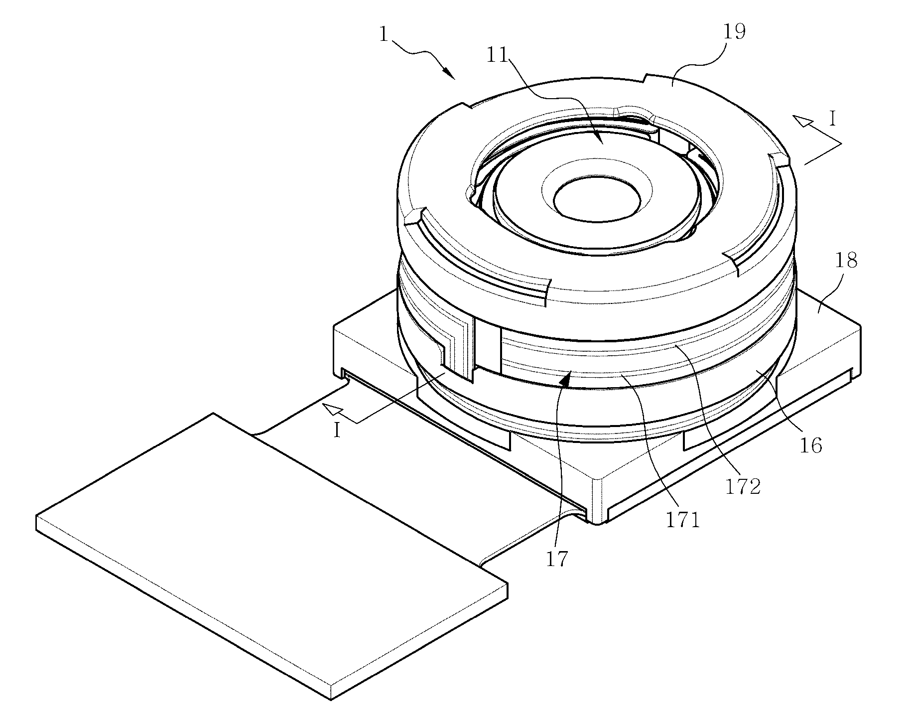
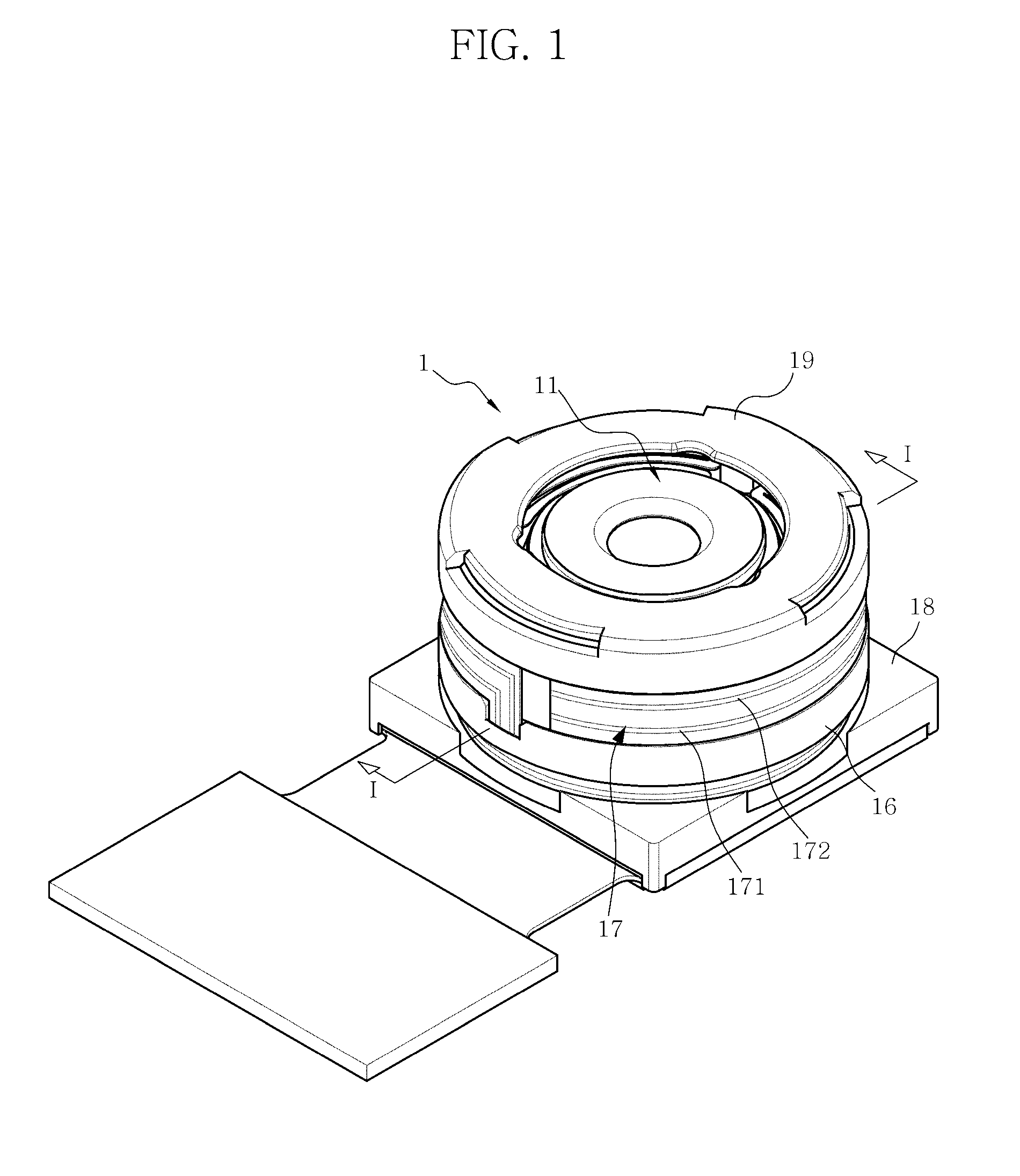
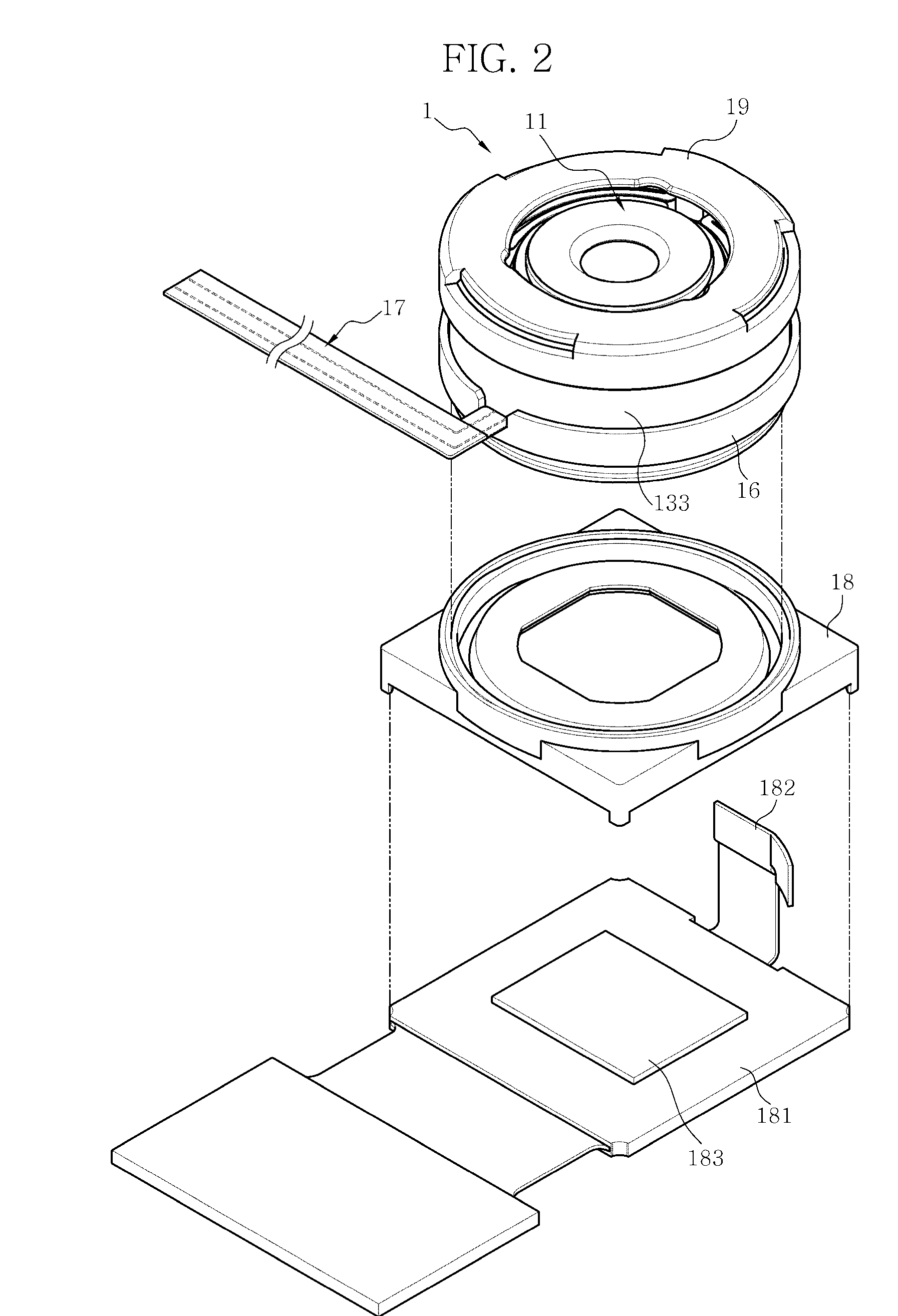
[0040]FIG. 1 is a perspective view illustrating a camera module according to an exemplary embodiment of the present invention. FIG. 2 is a perspective view illustrating a state in which a terminal extension section is unbound from an outer circumferential surface of a magnet section. FIG. 3 is an exploded perspective view illustrating the camera module of FIG....


PUM


Abstract

Provided is a camera module that includes a lens section comprising at least one lens, a coil section fixed to the lens section and comprising wiring terminals, a magnet section comprising a permanent magnet, an inner yoke, and an outer yoke, wherein the inner yoke and the outer yoke induce a magnetic force line to pass through the coil section, and a terminal extension section comprising a first terminal and a second terminal that electrically extend from the wiring terminals of the coil section to the outside of the camera module and surround the magnet section so that the first terminal and the second terminal are externally exposed.

Description

CROSS-REFERENCE TO RELATED APPLICATION[0001]This application claims the benefit under 35 U.S.C. §119(a) of Korean Patent Application Nos. 10-2009-0112206, filed on Nov. 19, 2009, and 10-2010-0096667, filed on Oct. 5, 2010, the disclosures of which are incorporated herein by references for all purposes.BACKGROUND[0002]1. Field of the Invention[0003]The present invention relates to a camera module, and more particularly, to a camera module that is mounted in a terminal and has a function of automatically focusing a subject.[0004]2. Description of the Related Art[0005]A camera module mounted in a small-sized terminal such as digital cameras or portable phones employs an image sensor of a charge coupled apparatus (CCD) type or a complementary metal oxide semiconductor (CMOS) type. The camera module converts an optical signal into an electrical signal to form an image.[0006]The camera module has an autofocus function of automatically focusing a subject. To this end, the camera module wit...

Claims


Application Information

Patent Timeline
IPC IPC(8): G02B7/04
CPCG02B7/026G03B3/10H02K5/225H04N5/23212H04N5/2254H04N5/2257H02K41/0356H04N23/57H04N23/55
Inventor LIM, JANG-HO
Owner MCNEX
Why Eureka
Try Eureka