Variable wavelength interference filter, optical module, spectroscopic analyzer, and analyzer

Inactive Publication Date: 2012-07-26
SEIKO EPSON CORP
View PDF7 Cites 9 Cited by
  • Summary
  • Abstract
  • Description
  • Claims
  • Application Information

AI Technical Summary

Benefits of technology

[0011]An advantage of some aspects of the invention is that it provides a variable wavelength interference filter having a simple structure capable of suppressing a decrease of resolution even when the gap dimension between reflecting films is changed and capable of making the connection of wirings easy, an optical module and a spectroscopic analyzer each including the variable wavelength interference filter.

Problems solved by technology

This operation is complicated.
Thus, the electrostatic attractive force is uneven.
When wirings are laid out with a small force in order to prevent detachment or deformation of the substrates, the wiring reliability may decrease.

Method used


Image

  • Variable wavelength interference filter, optical module, spectroscopic analyzer, and analyzer
  • Variable wavelength interference filter, optical module, spectroscopic analyzer, and analyzer
  • Variable wavelength interference filter, optical module, spectroscopic analyzer, and analyzer

Examples


first embodiment

5. Operation and Effect of First Embodiment

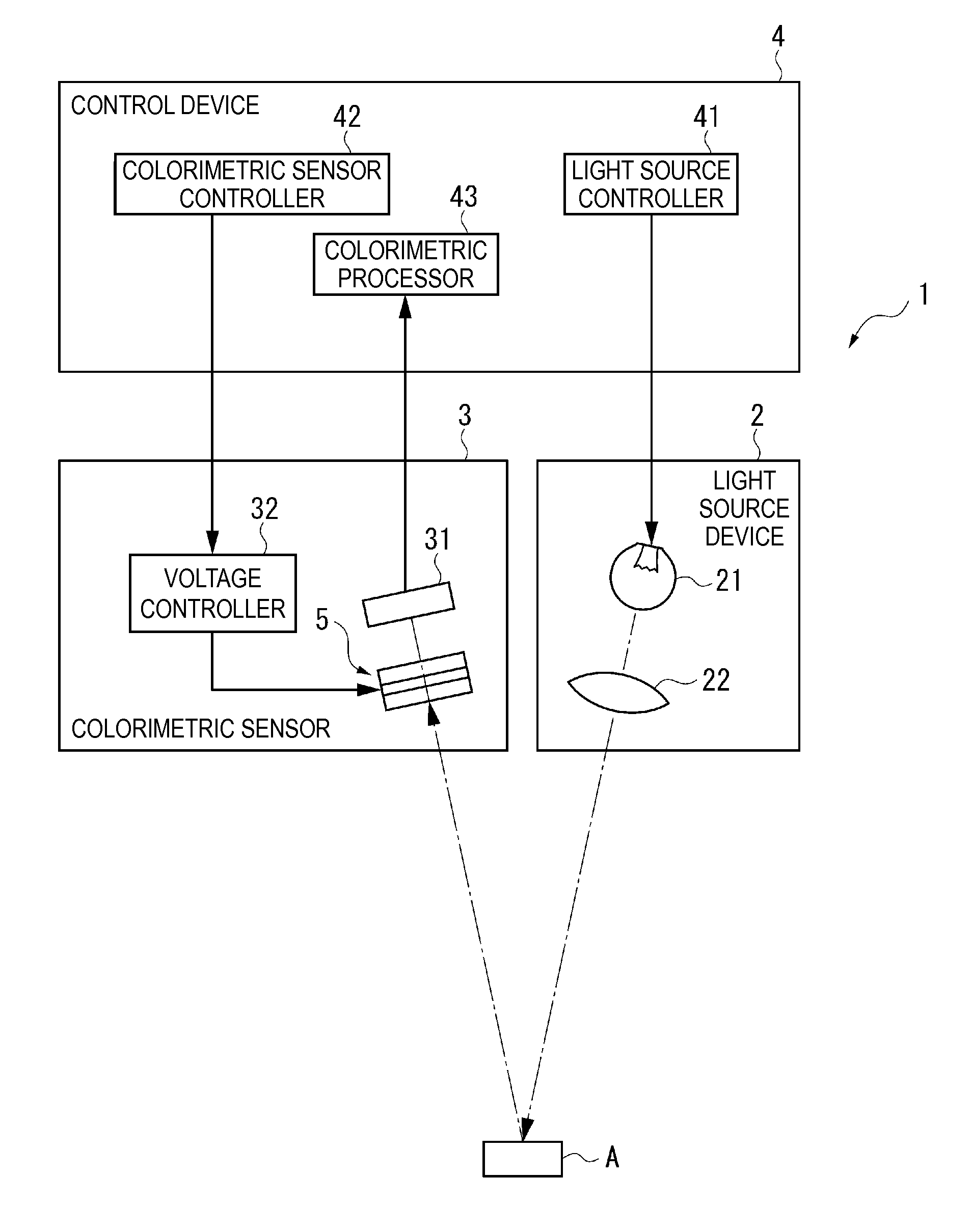
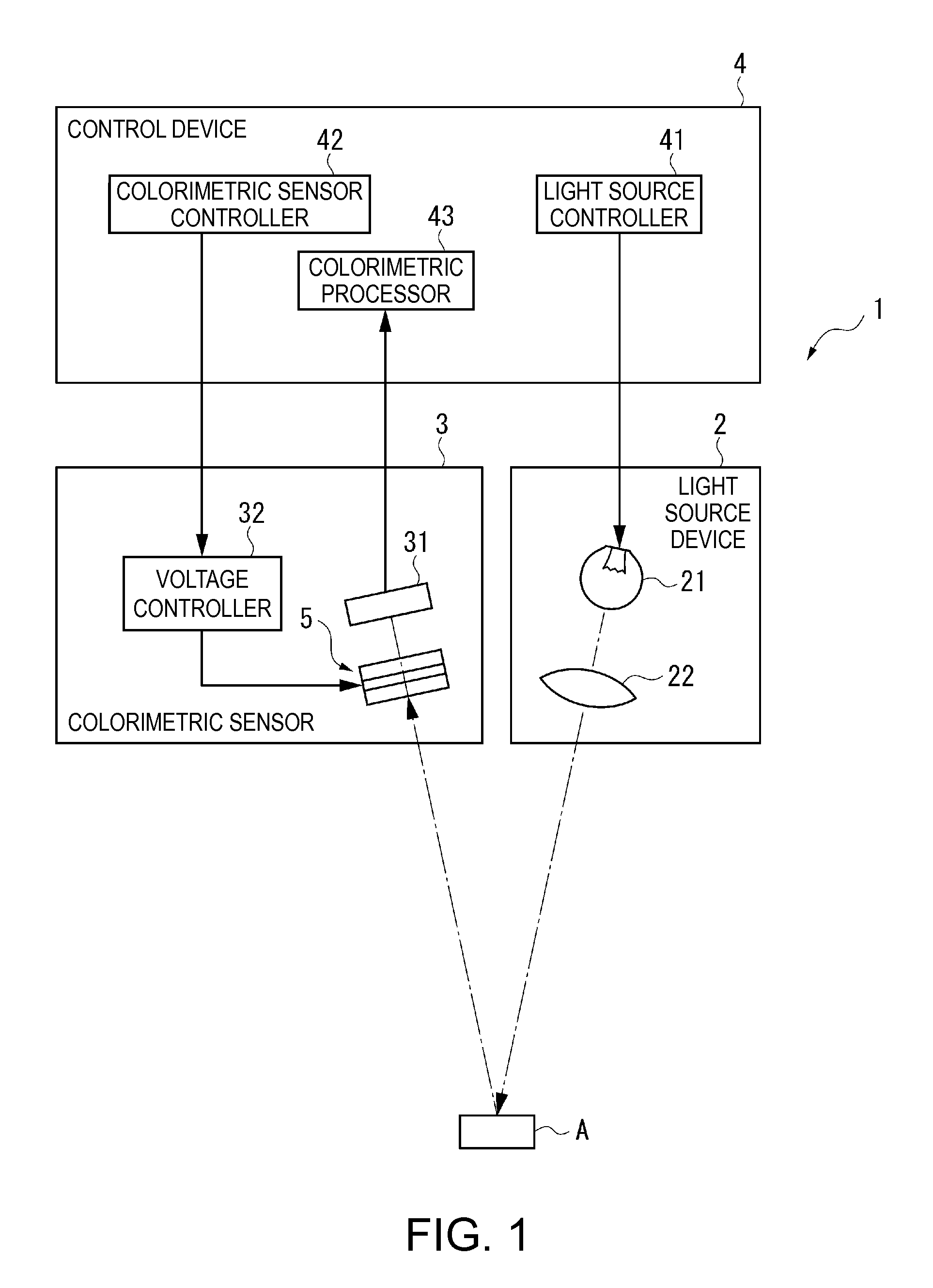
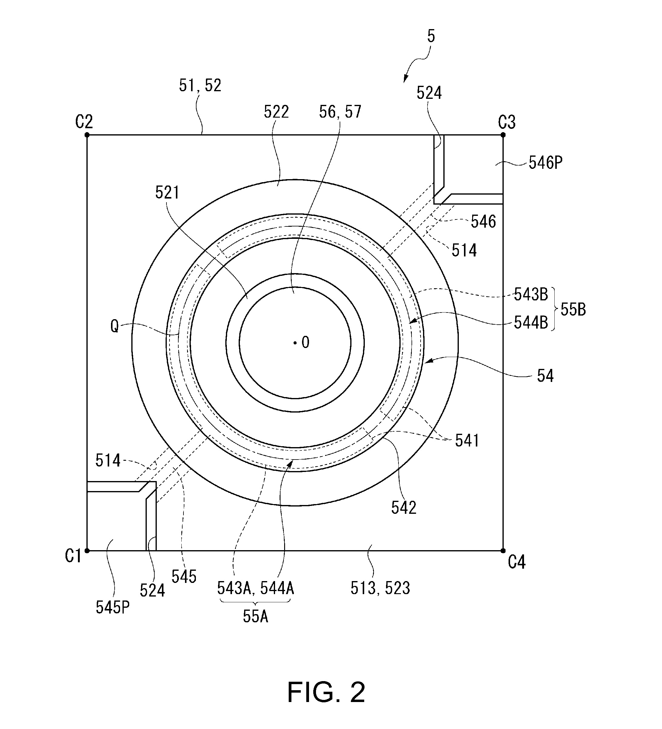
[0103]As described above, the variable wavelength interference filter 5 of the above embodiment is formed in a ring shape in which the fixed electrode 541 is made up of the first and second fixed partial electrodes 543A and 543B electrically isolated from each other, and the movable electrode 542 includes the first facing region 544A facing the first fixed partial electrode 543A and the second facing region 544B facing the second fixed partial electrode 543B. Moreover, the first extraction electrode 545 is formed in the first fixed partial electrode 543A, and the second extraction electrode 546 is formed in the second fixed partial electrode 543B.

[0104]In such a configuration, by applying a driving voltage between the first electrode pad 545P of the first extraction electrode 545 and the second electrode pad 546P of the second extraction electrode 546, it is possible to drive the first partial actuator 55A which is made up of the first fixe...

second embodiment

7. Operation and Effect of Second Embodiment

[0126]The variable wavelength interference filter 5A of the second embodiment provides the same effects as the variable wavelength interference filter 5 of the first embodiment.

[0127]That is, by applying a driving voltage between the first electrode pad 545P of the first extraction electrode 545 and the second electrode pad 546P of the second extraction electrode 546, it is possible to drive the partial actuators 55C and 55D.

[0128]Moreover, since the first and second electrode pads 545P and 546P are formed on the fixed substrate 51, the wiring operation can be easily performed from the movable substrate 52 side of the variable wavelength interference filter 5A when incorporating the variable wavelength interference filter 5A into the colorimetric sensor 3. Moreover, since no stress is applied to the movable substrate 52 during the wiring operation, detachment between the fixed substrate 51 and the movable substrate 52 and tilting of the mo...


PUM


Abstract

A variable wavelength interference filter includes a fixed substrate having a fixed reflecting film, a movable substrate having a movable reflecting film, and an electrostatic actuator including a fixed electrode and a movable electrode. The fixed electrode includes first and second fixed partial electrodes electrically isolated from each other. First and second extraction electrodes extending from the first and second fixed partial electrodes, respectively, are formed on the fixed substrate. The movable electrode is formed in a ring shape covering first and second facing regions facing the first and second fixed partial electrodes, respectively.

Description

BACKGROUND[0001]1. Technical Field[0002]The present invention relates to a variable wavelength interference filter that acquires light of a specific wavelength, an optical module, and a spectroscopic analyzer.[0003]2. Related Art[0004]In the related art, a variable wavelength interference filter (optical filter device) that extracts light of a specific wavelength from light having a plurality of wavelengths is known (for example, see JP-A-2009-251105).[0005]The variable wavelength interference filter (optical filter device) disclosed in JP-A-2009-251105 includes a first substrate which has a movable portion (first portion) and a diaphragm (second portion) supporting the movable portion, and a second substrate that faces the first substrate. Moreover, a movable mirror is formed in the movable portion of the first substrate, and a fixed mirror is formed on a surface of the second substrate facing the movable portion. A ring-shaped electrode is formed on each of the first and second su...

Claims


Application Information

Patent Timeline
IPC IPC(8): G01J3/45G02B5/28G01B9/02
CPCG01J3/027G01J3/10G02B26/001G01J3/51G01J3/26
Inventor HIROKUBO, NOZOMU
Owner SEIKO EPSON CORP
Why Eureka
Try Eureka