
Magnetic resonance imaging device

a magnetic resonance imaging and device technology, applied in the field of magnetic resonance imaging technique, can solve problems such as degrading image quality, and achieve the effect of improving image quality and good precision

Active Publication Date: 2011-05-12
FUJIFILM HEALTHCARE CORP
View PDF7 Cites 13 Cited by
  • Summary
  • Abstract
  • Description
  • Claims
  • Application Information

AI Technical Summary

Benefits of technology

The present invention provides a technique for correcting distortion of k-space data in diffusion-weighted imaging caused by eddy currents and vibrations. The technique uses a gradient magnetic field pulse to emphasize the diffusion of water molecules in the brain. However, the strengths of the read-out gradient magnetic field pulse and the phase encoding gradient magnetic field pulse are not zero at the time of measuring the eddy current, resulting in fluctuation of magnetic field. This fluctuation affects the image quality, causing distortion of k-space data. The present invention provides a technique for calculating characteristic data for correcting this distortion for each position in a slice direction, improving image quality in the diffusion-weighted imaging.

Problems solved by technology

Since the MPG pulse generally has a higher strength and is applied for a relatively longer time, eddy currents and vibrations thereby induced result in fluctuation of magnetic field, which eventually degrades image quality.

Method used


Image

  • Magnetic resonance imaging device
  • Magnetic resonance imaging device
  • Magnetic resonance imaging device

Examples


first embodiment

[0034]The first embodiment of the present invention will be explained below. Hereafter, in all the drawings for explaining embodiments of the present invention, elements having the same function are indicated with the same symbols, and repetition of explanation thereof is omitted.

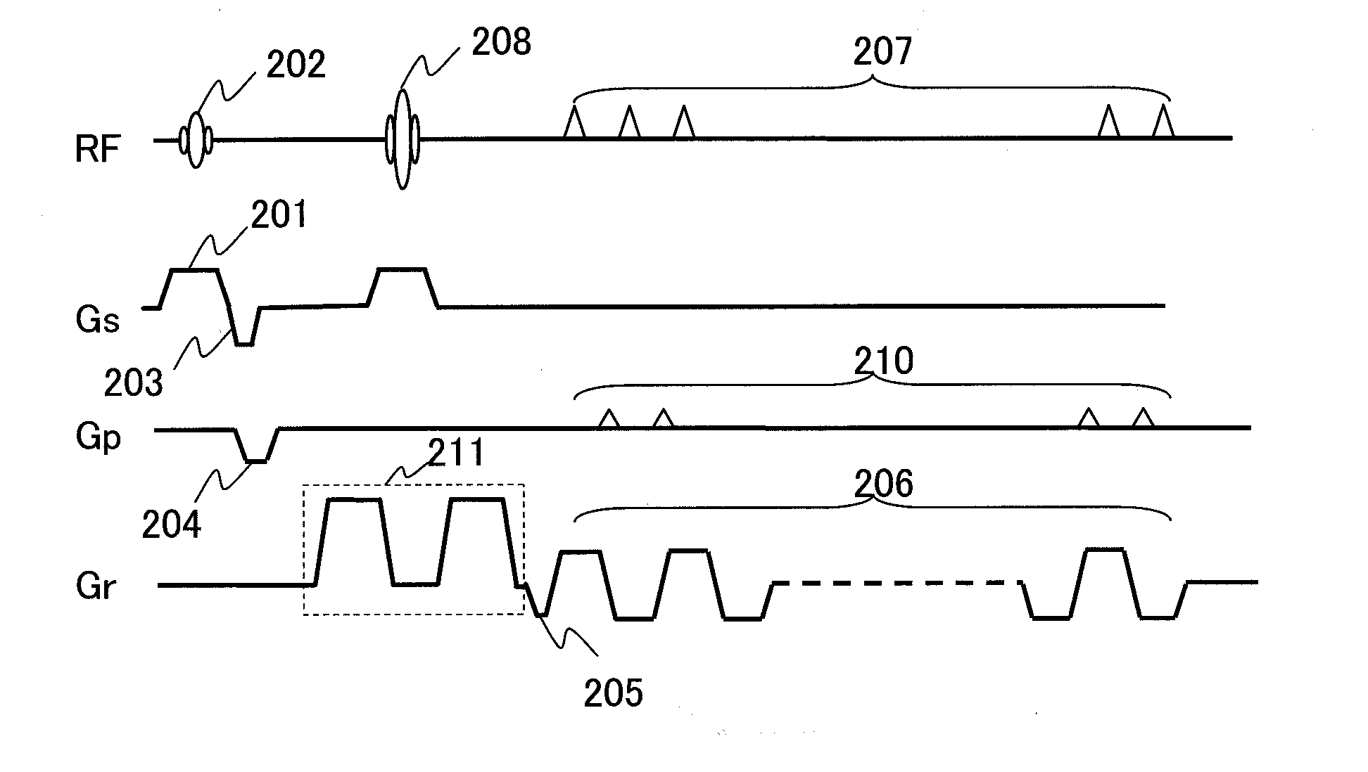
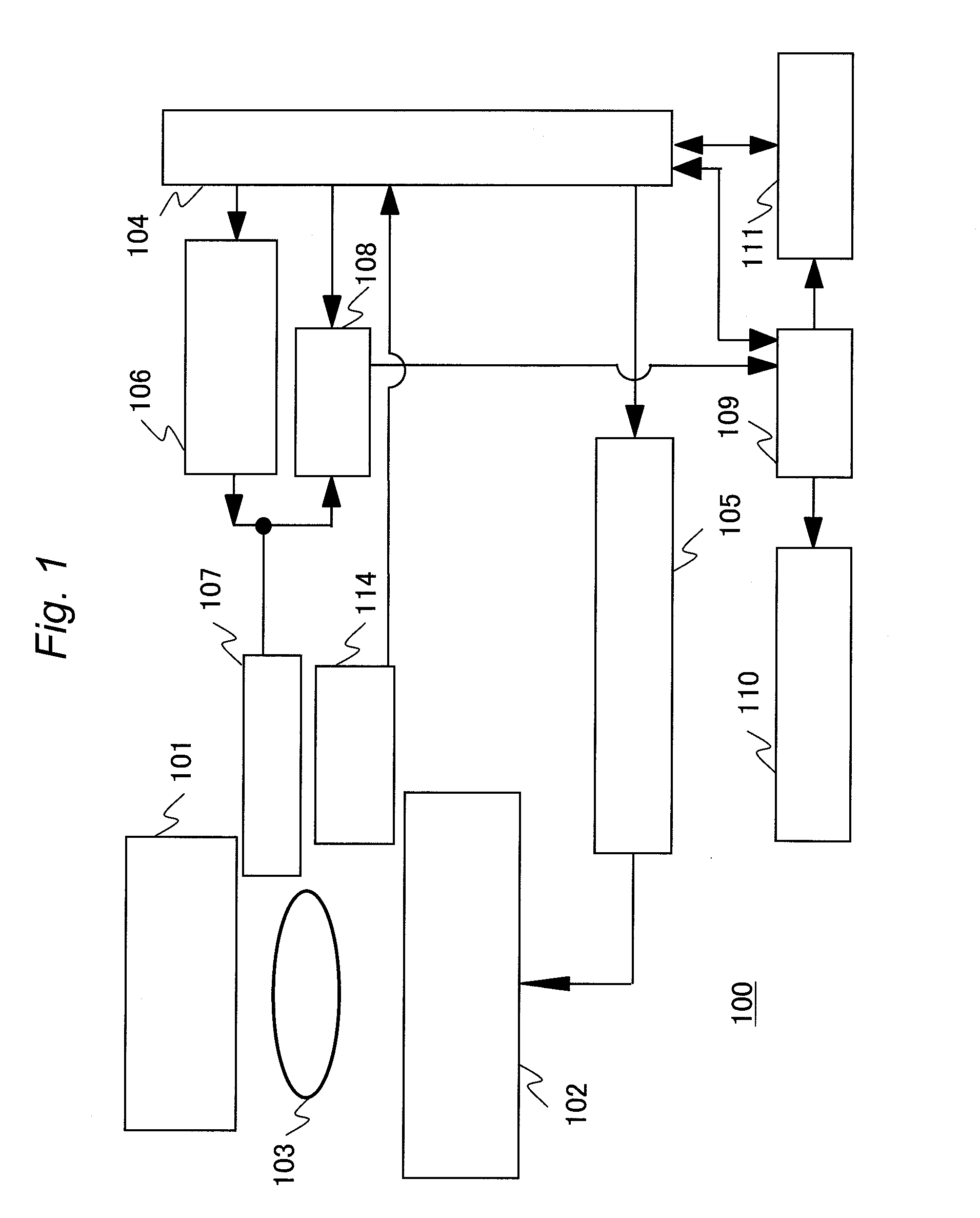
[0035]First, an MRI device of this embodiment will be explained. FIG. 1 is a block diagram showing a schematic configuration of an MRI device 100 of this embodiment. The MRI device 100 is provided with a magnet 101 for generating a static magnetic field, a gradient coil 102 for generating a gradient magnetic field, a sequencer 104, a gradient magnetic field power supply 105, a radio frequency magnetic field generator 106, a probe 107 for irradiating a radio frequency magnetic field and detecting magnetic resonance signals, a receiver 108, a computer 109, a display 110, and a storage medium 111. A subject (for example, living body) 103 is placed on a bed (patient table) in a space applied with a static magne...


PUM


Abstract

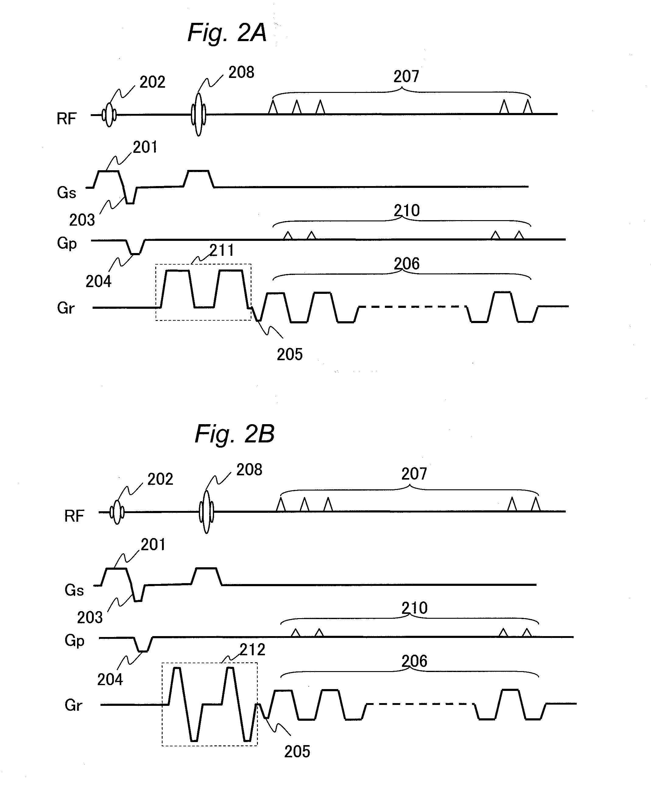
In the diffusion-weighted imaging, amounts of distortion and amounts of phase offset of k-space data due to a temporally changing magnetic field error induced by eddy currents and vibrations associated with application of a diffusion-weighted gradient magnetic field pulse are corrected with good precision to improve image quality. Characteristic data for correcting distortion of k-space data are calculated for every position in the slice direction as peak shifts of projections observed between the cases of applying and not applying an MPG pulse. As the characteristic data, amounts of distortion in the read-out direction and the phase encoding direction and phase offset amounts in a slice plane are calculated.

Description

TECHNICAL FIELD[0001]The present invention relates to a magnetic resonance imaging technique. In particular, the present invention relates to a technique for correcting influences of fluctuation of magnetic field originating in eddy current and vibration in diffusion-weighted imaging.BACKGROUND ART[0002]A magnetic resonance imaging (MRI) device is a medical diagnostic imaging device, which applies a radio frequency magnetic field and a gradient magnetic field to a subject placed in a static magnetic field, detects signals generated by nuclear magnetic resonance in the subject, and forms an image from the signals.[0003]As a method capable of obtaining images in which cerebral infarction at an acute stage, tumors etc. are emphasized with high signal strength, there is the diffusion-weighted imaging in which imaging is performed with emphasizing diffusion of water molecules. Since cerebral infarction at an acute stage is in a state of cellular edema, such diffusion is suppressed. Furth...

Claims


Application Information

Patent Timeline
Patent Type & Authority Applications(United States)
IPC IPC(8): A61B5/055
CPCA61B5/055A61B5/7257G01R33/56563G01R33/56341G01R33/56518G01R33/5616
Inventor TANIGUCHI, YOBITO, YOSHITAKAMIYAWAKI, SHOICHITAKEUCHI, HIROYUKIYOKOSAWA, SUGURU
Owner FUJIFILM HEALTHCARE CORP
Learn More