
Microphone Assembly with Integrated Self-Test Circuitry

a microphone and circuit technology, applied in the direction of transducer details, electrostatic transducer microphones, electrical transducers, etc., can solve the problems of difficult testing of sensitive analog circuits, such as low-noise miniature microphone preamplifiers

Active Publication Date: 2011-05-12
TDK CORPARATION
View PDF1 Cites 42 Cited by
  • Summary
  • Abstract
  • Description
  • Claims
  • Application Information

AI Technical Summary

Benefits of technology

[0006]The test mode of the assembly facilitates that digital or analog miniature condenser microphone assemblies may be sorted into different groups, such as for example “Approved”, “Rejected”, “A quality” and “B quality”. The test mode enables accurate and fast measurements of the output noise level in an industrial environment involving high environmental noise levels. Thus, according to the present invention, there is no need for anechoic test environments. In this way, automated tests of noise performance can be performed in a fast and cost-effective manner in connection with normal electrical tests.
[0007]The test mode allows selective measurement and assessment of signals generated by the signal processing circuitry without influence from signals generated by the electro-acoustic transducer element. By doing this accurate identification of a failing component or part of a rejected miniature microphone assemblies is facilitated. As explained in greater detail later, the test mode facilitates measurements of the performance or electrical characteristics of the signal processing circuitry, typically arranged on a semiconductor die in the form of an ASIC, on the finished condenser microphone assembly.
[0013]The mode-setting circuitry of the condenser microphone assembly may comprise an electronic switch adapted to electrically disconnecting the transducer element from the signal processing circuitry. Moreover, a capacitor may be provided that is electrically connected to the signal processing circuitry when the condenser microphone assembly is operated in the test mode. Preferably, the provided capacitor has a capacitance essentially equal to a capacitance formed by diaphragm and the back plate structures of the electro-acoustic transducer element. The capacitor preferably couples to the signal processing circuitry in a manner that keeps a signal source capacitance as “seen” by the signal processing circuitry in the test mode essentially identical to the transducer capacitance in the operational mode. This allows performance characteristics of the signal processing circuitry, for example a preamplifier, to be tested under realistic operational conditions, i.e., with a signal source impedance substantially identical to that of the operational mode.
[0016]The condenser microphone assembly facilitates that a supply voltage level and / or current supply level to the signal processing circuitry may be essentially independent of a mode-setting of the assembly. In particular, a supply voltage level or current supply level to a preamplifier circuitry of the signal processing circuitry may be essentially independent of a mode-setting of the assembly. Thus, an essentially constant supply voltage and / or an essentially constant current may be applied to the signal processing circuitry in both the test mode and the operationally mode. This allows the performance characteristics of the preamplifier circuitry to be tested under realistic operational conditions, i.e. with supply voltage and current settings substantially identical to those of the operational mode.
[0021]The method facilitates that a supply voltage level to the signal processing circuitry may be essentially independent of a mode-setting of the assembly. In particular, a supply voltage level to a preamplifier circuitry of the signal processing circuitry may be essentially independent of a mode-setting of the assembly. Thus, an essentially constant supply voltage and / or an essentially constant current may be applied to the signal processing circuitry in both the test mode and the operationally mode.

Problems solved by technology

Sensitive analog circuits, such as low-noise miniature microphone preamplifiers, are generally difficult to test during wafer manufacturing due to electromagnetic and acoustical noisy and hostile fabrication environments.

Method used


Image

  • Microphone Assembly with Integrated Self-Test Circuitry
  • Microphone Assembly with Integrated Self-Test Circuitry
  • Microphone Assembly with Integrated Self-Test Circuitry

Examples


first embodiment

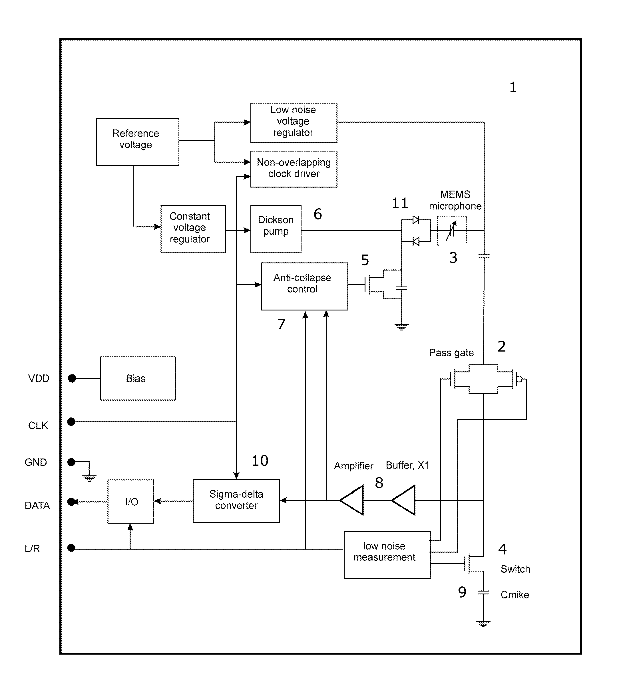
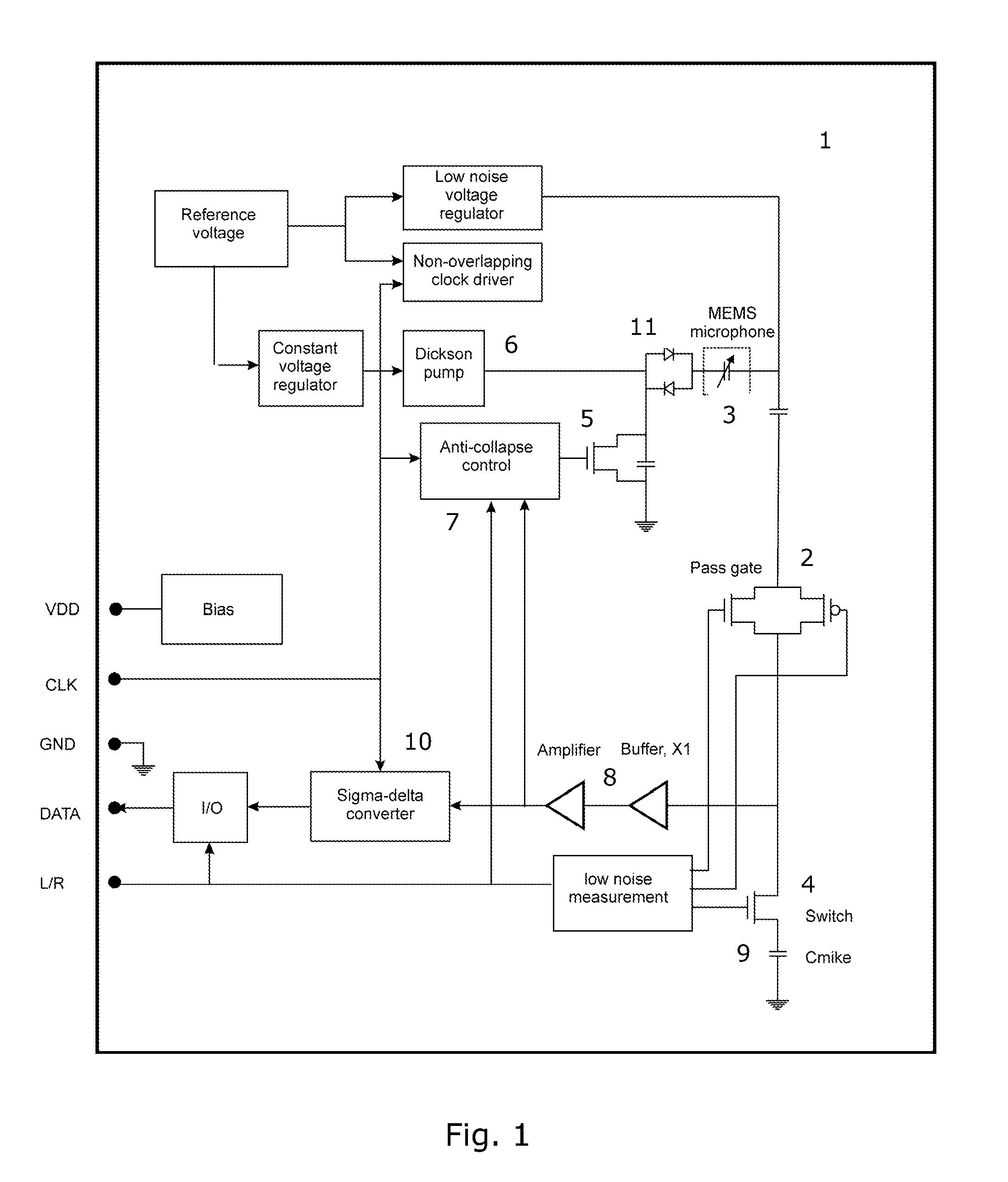
[0023]FIG. 1 shows a miniature microphone assembly according to the present invention;

second embodiment

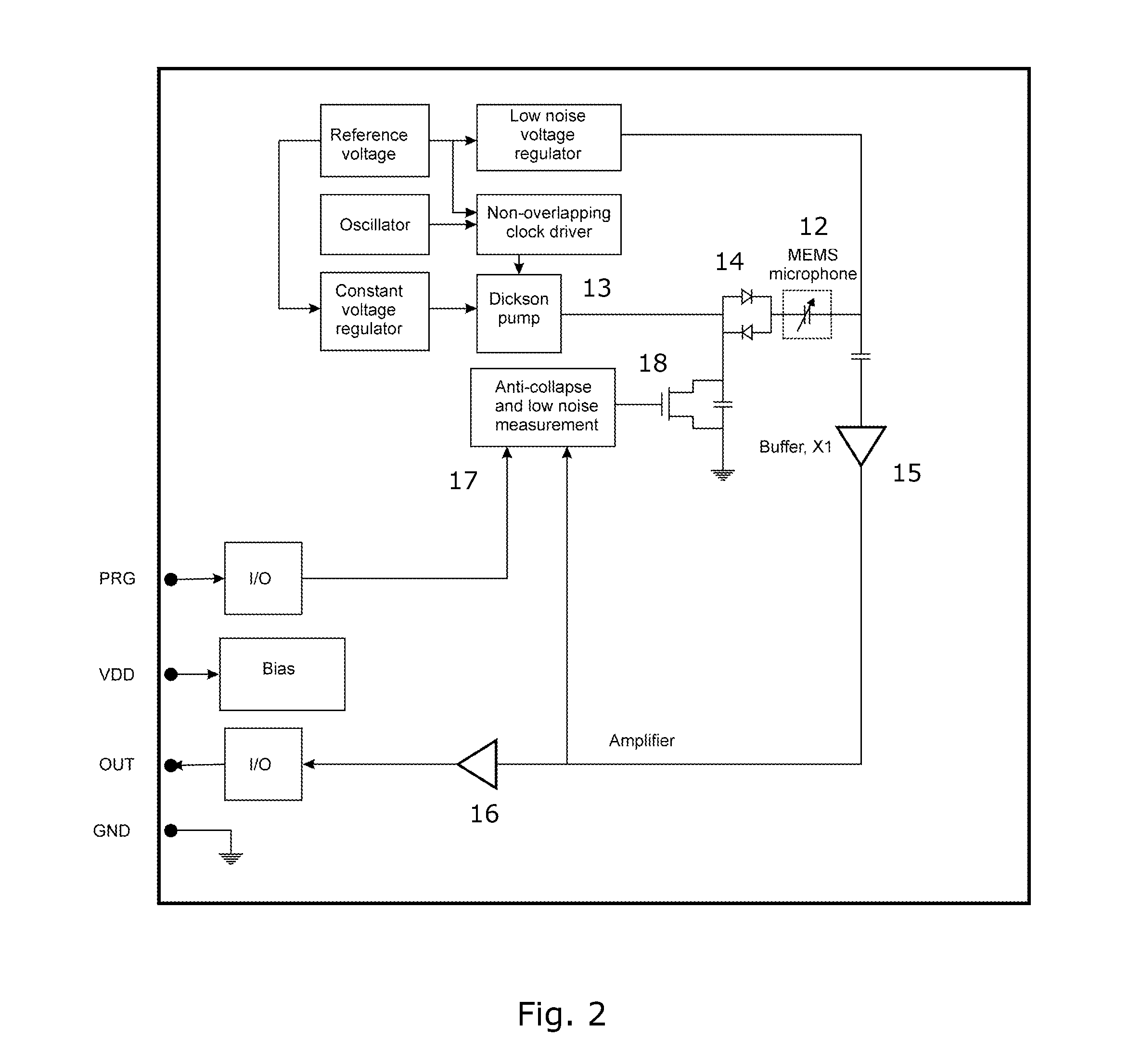
[0024]FIG. 2 shows a miniature microphone assembly according to the present invention; and

third embodiment

[0025]FIG. 3 shows a miniature microphone assembly according to the present invention.

[0026]While the invention is susceptible to various modifications and alternative forms, specific embodiments have been shown by way of example in the drawings and will be described in detail herein. It should be understood, however, that the invention is not intended to be limited to the particular forms disclosed. Rather, the invention is to cover all modifications, equivalents, and alternatives falling within the spirit and scope of the invention as defined by the appended claims.


PUM


Abstract

The present invention relates to a condenser microphone assembly comprising an electro-acoustic transducer element comprising a diaphragm and a back plate, signal processing circuitry operatively connected to the transducer element so as to process signals generated by the transducer element, and a mode-setting circuitry for selectively setting the condenser microphone assembly in a test mode or an operational mode. The electro-acoustic sensitivity of the condenser microphone assembly, when operated in the test mode, is at least 40 dB lower than the corresponding electro-acoustic sensitivity of the assembly when operated in the operational mode. The present invention further relates to a method for determining a performance parameter of a signal processing circuitry mounted inside a housing of an assembled condenser microphone assembly.

Description

FIELD OF THE INVENTION[0001]The present invention relates to a miniature microphone assembly and a method for measuring selected performance parameters of a signal processing circuitry of such a miniature microphone assembly. In particular, the present invention relates to a miniature microphone assembly comprising an integrated diagnostic or test circuitry for separating electric signals generated by the signal processing circuitry from signals generated by a microphone transducer element operatively connected to the signal processing circuitry.BACKGROUND OF THE INVENTION[0002]Sensitive analog circuits, such as low-noise miniature microphone preamplifiers, are generally difficult to test during wafer manufacturing due to electromagnetic and acoustical noisy and hostile fabrication environments. It is therefore advantageous to measure performance parameters of a signal processing circuitry during a final test of the assembled microphone assembly. Also, due to variability during prod...

Claims


Application Information

Patent Timeline
IPC IPC(8): H04R3/00
CPCH04R19/005H04R29/004H04R19/04H04R19/016
Inventor HOVESTEN, PER F.POULSEN, JENS KRISTIANROCCA, GINO
Owner TDK CORPARATION
Learn More