
Method of fabricating a semiconductor device

a semiconductor and device technology, applied in semiconductor devices, capacitors, electrical devices, etc., can solve the problems of unavoidable decrease in yield, increase in cost relative to basic process cost, and complicated device structure, and achieve high density structure and sufficient capacity

Inactive Publication Date: 2011-05-05
ELPIDA MEMORY INC
View PDF0 Cites 2 Cited by
  • Summary
  • Abstract
  • Description
  • Claims
  • Application Information

AI Technical Summary

Benefits of technology

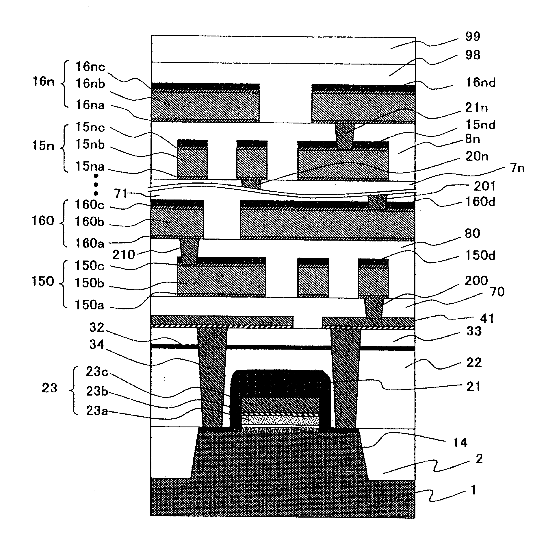
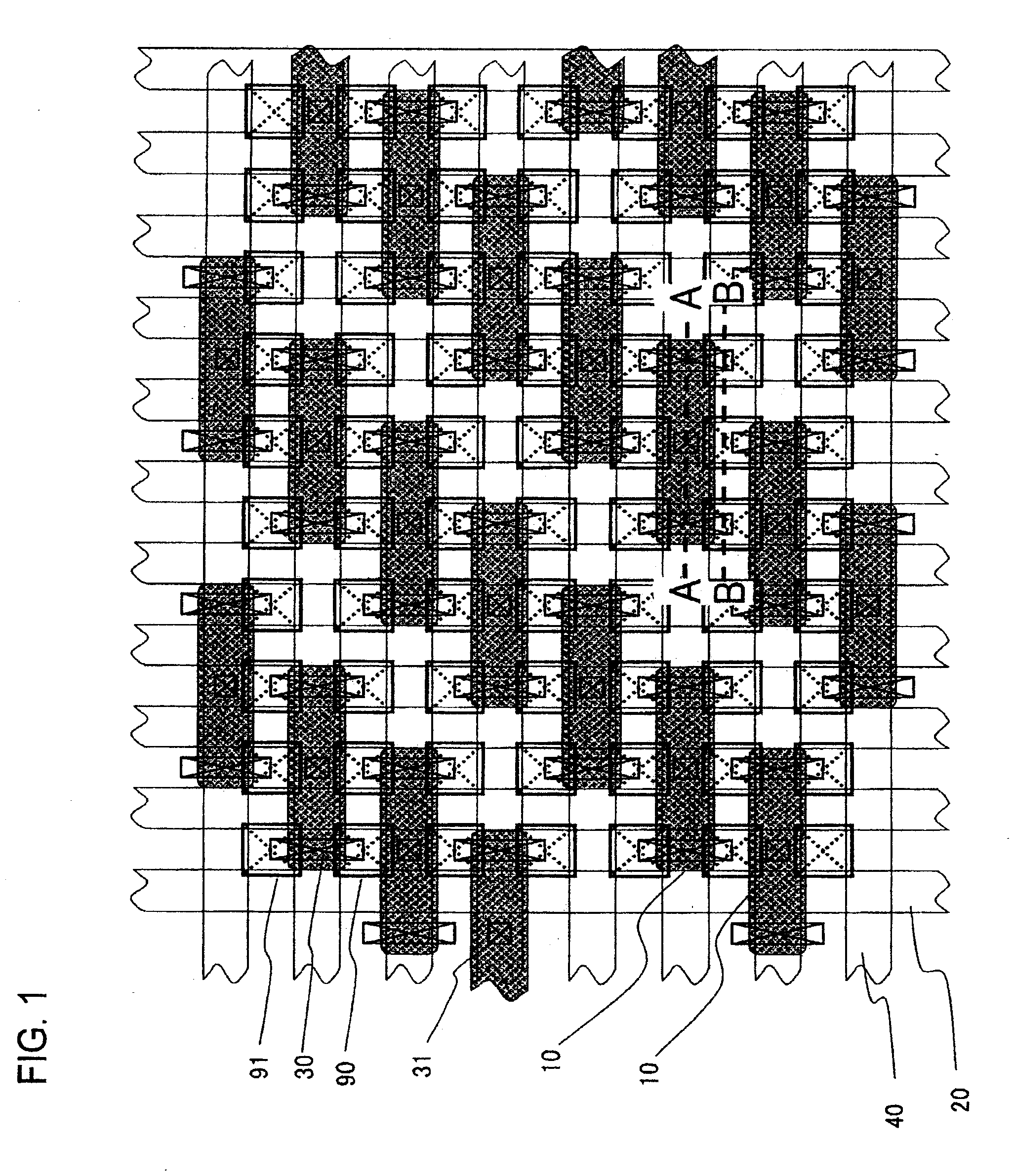
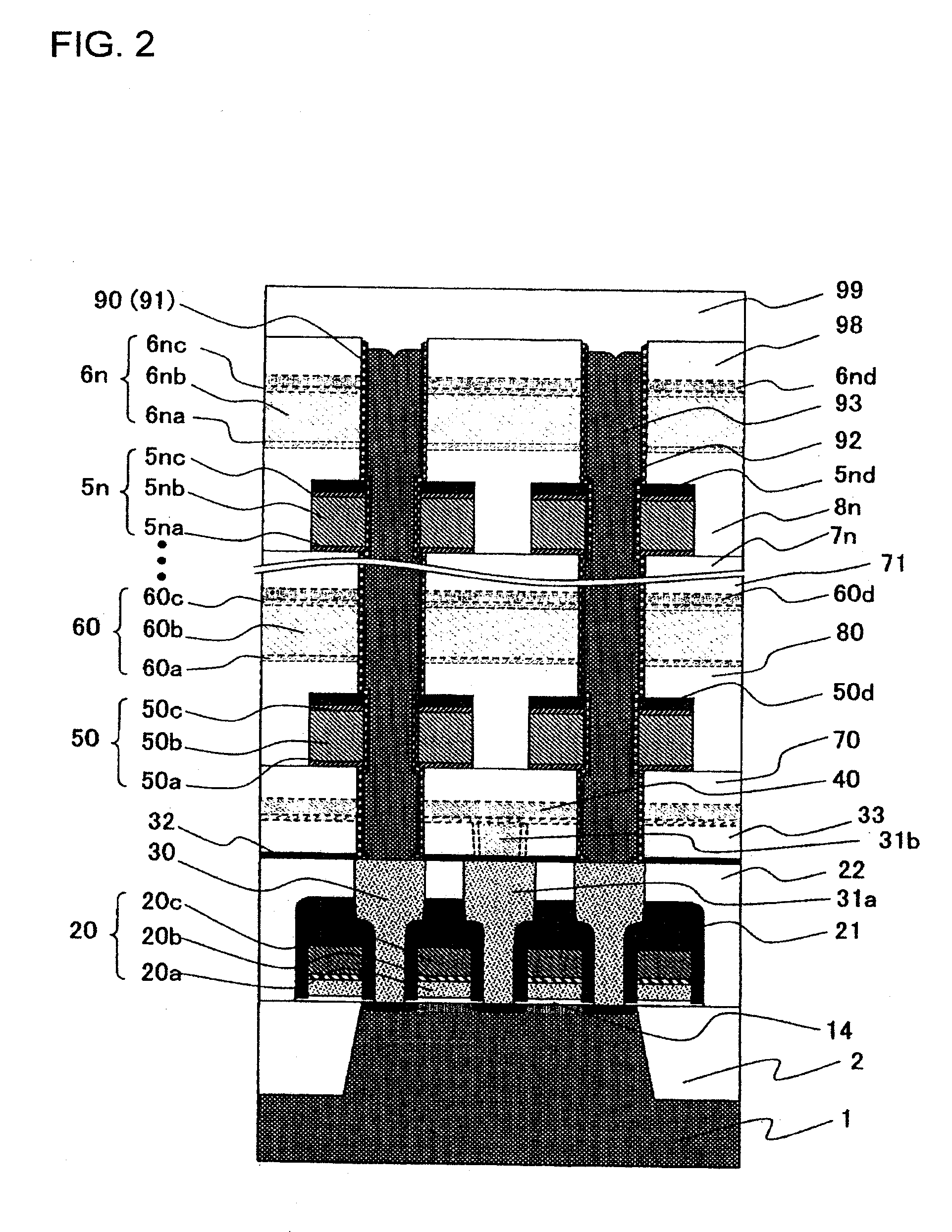
The present invention provides a semiconductor device with a high-density structure that can be easily formed. The semiconductor device includes a transistor and a capacitor, and a memory cell array with a matrix arrangement of the transistor and capacitor. The semiconductor device also includes a peripheral circuit with a transistor and a gate electrode. The memory cell array and peripheral circuit have interconnection wires and conductive plugs for forming capacitors. The interconnection wires and conductive plugs are made using the same material. The technical effects of the present invention are that it provides a semiconductor device with a high-density structure and easy-to-form memory cell array and peripheral circuit.

Problems solved by technology

The capacitor accordingly has a section with an increased aspect ratio and the device structure is complicated.
Thus, it has been difficult to fabricate the device and to ensure both of a required capacitance and a satisfactory yield compatibly.
Thus, an increase in cost relative to the basic process cost and a decrease in yield are unavoidable.
Accordingly, the proportion of the region in which only the through-hole extends has increased in the peripheral circuit region generation by generation, which forms a factor in lowering the performance of the basic device, such as an increase in through-hole resistance.
For this reason, it is difficult to provide the peripheral circuit with a necessary and sufficient number of interconnection layers.
Thus, the performance of the peripheral circuit cannot sufficiently be improved.
In addition, separate formations of the capacitor and the interconnection wires constitute a cost increasing factor.
For the reasons stated above, it is difficult to realize a logic LSI with a large-capacity embedded DRAM at a low cost.

Method used


Image

  • Method of fabricating a semiconductor device
  • Method of fabricating a semiconductor device
  • Method of fabricating a semiconductor device

Examples


Embodiment Construction

Hereinafter, an exemplary embodiment of the present invention will be described.

A semiconductor device in accordance with the present embodiment has a structure that includes a layered region in which a capacitor element is formed (i.e., capacitor region), and in the capacitor region, an interconnection layer is formed such that the interconnection layer is utilized as a counter electrode of the capacitor element. The semiconductor device can accordingly ensure a sufficient storage capacitance and an increased density compatibly.

In a DRAM capacitor of the device in accordance with the present embodiment, an exclusive electrode common to all the cells is not used as a counter electrode, which is opposed to a storage electrode, but an interconnection wire extending through the capacitor region is used as the counter electrode. Accordingly, this interconnection wire can be utilized as an interconnection wire in a peripheral circuit region as well. For this reason, a necessary interconn...


PUM


Abstract

A semiconductor device includes: a transistor including source and drain diffusion-layers, a gate insulating film and a gate electrode; first and second plugs formed in a first interlayer-insulating film and connected to the source and drain diffusion-layers, respectively; a third plug extending through a second interlayer-insulating film and connected to the first plug; a first interconnection-wire formed on the second interlayer-insulating film and connected to the third plug; a second interconnection-wire formed on a third interlayer-insulating film and intersecting the first interconnection-wire; a fourth interlayer-insulating film; a hole extending through the fourth, third and second interlayer-insulating films, the hole being formed such that a side surface of the second interconnection-wire is exposed; and a fourth plug filling the hole via an intervening dielectric film and connected to the second plug, wherein a capacitor is formed using the fourth plug, the second interconnection-wire and the dielectric film sandwiched therebetween.

Description

BACKGROUND OF THE INVENTION1. Field of the InventionThe present invention relates to a semiconductor device and a method of fabricating the same.2. Description of the Related ArtIn conventional DRAM (Dynamic Random Access Memory) of the STC (Stacked Capacitor Cell) type, a capacitor has been made to have a three-dimensional structure, thus having an increased surface area in the height direction, in order to compensate for a decrease in the electric capacitance of the capacitor with miniaturization. The capacitor accordingly has a section with an increased aspect ratio and the device structure is complicated. Thus, it has been difficult to fabricate the device and to ensure both of a required capacitance and a satisfactory yield compatibly. An exemplary conventional capacitor structure is disclosed in Japanese Patent Laid-Open No. 2004-71759.On the other hand, the number of interconnection layers is increasing as the capability and the performance of a semiconductor device become hi...

Claims


Application Information

Patent Timeline
Patent Type & Authority Applications(United States)
IPC IPC(8): H01L21/768H10N97/00
CPCH01L21/8221H01L27/0688H01L28/90H01L27/10852H01L27/10814H10B12/315H10B12/033
Inventor UCHIYAMA, HIROYUKI
Owner ELPIDA MEMORY INC
Learn More