
Millimeter Wave Concealed Object Detection System Using Portal Deployment

Inactive Publication Date: 2011-05-05
MICROSEMI
View PDF12 Cites 28 Cited by
  • Summary
  • Abstract
  • Description
  • Claims
  • Application Information

AI Technical Summary

Benefits of technology

[0005]In one embodiment, the disclosed system is an approach for deploying a concealed object detection system using pre-engineered and pre-manufactured components to effectively control the deployment surroundings and provide a known environment in which the equipment can operate. The system provides inherent background/perip

Problems solved by technology

However, such access control systems are not suitable for the deployment of concealed object detection systems which include magnetometer or biometric technologies or imaging systems utilizing various forms of energy including millimeter waves, radio waves, visible light, infrared, ultraviolet, and microwave energy.

Method used


Image

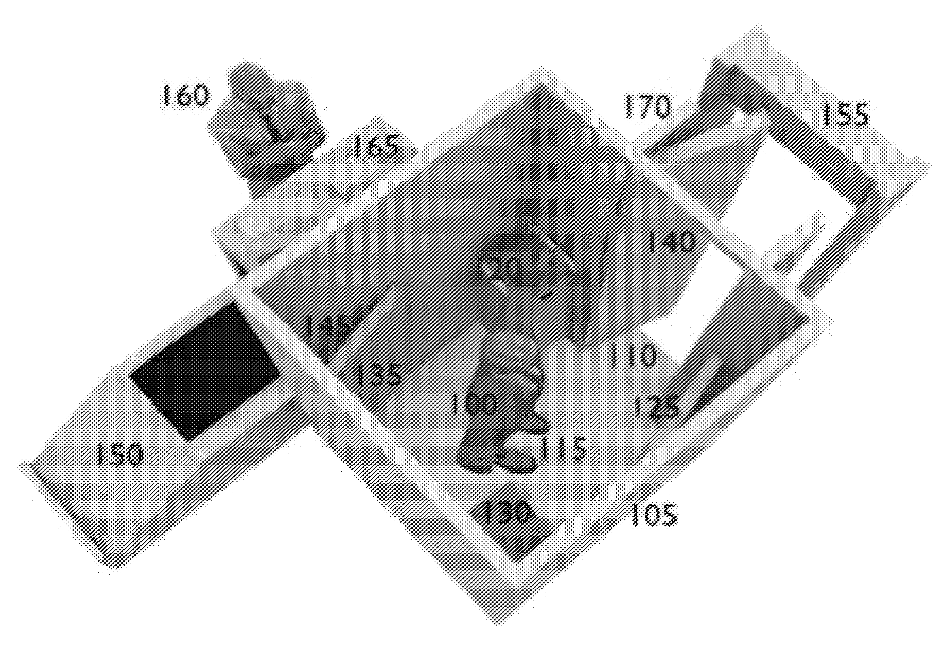
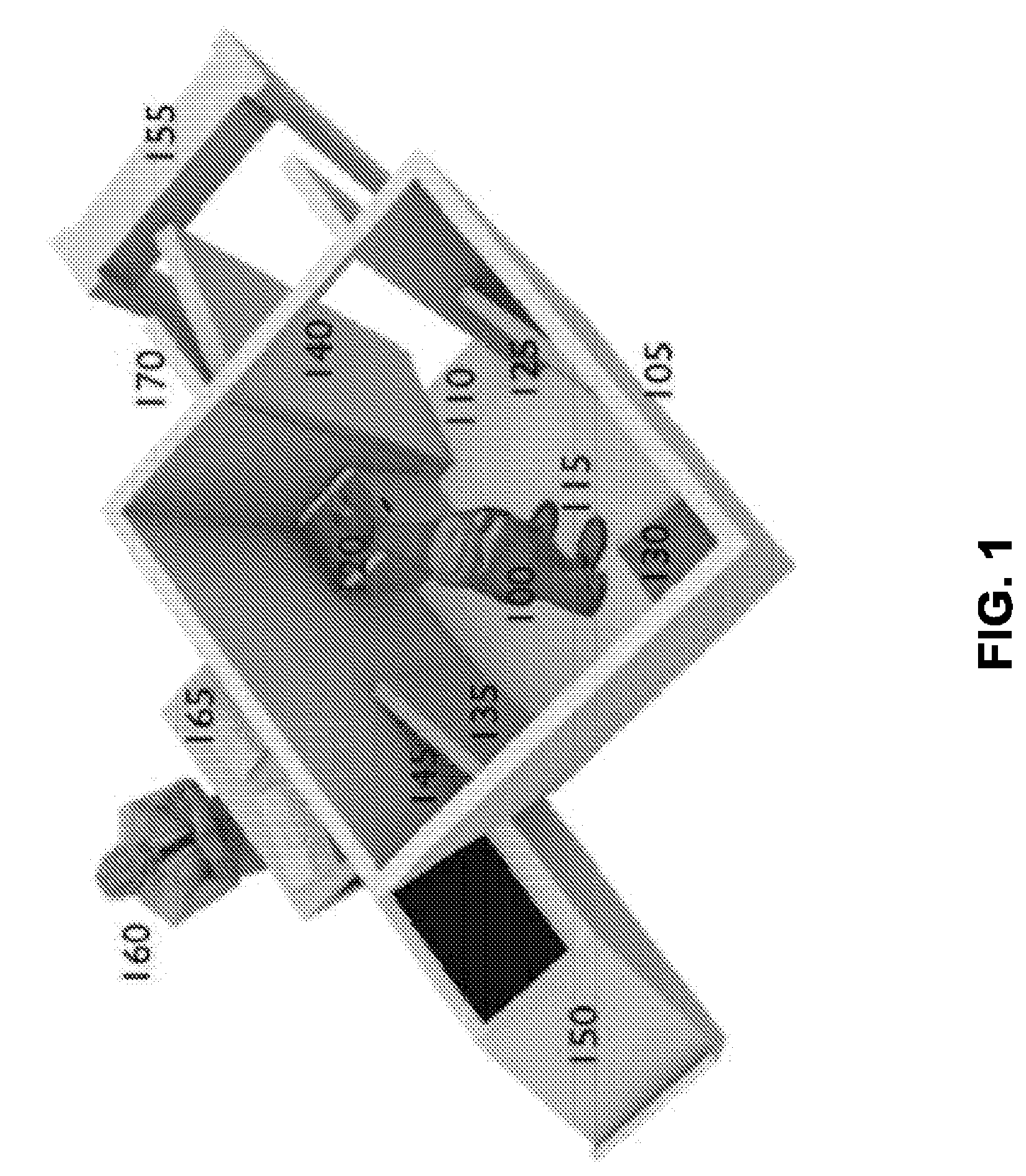
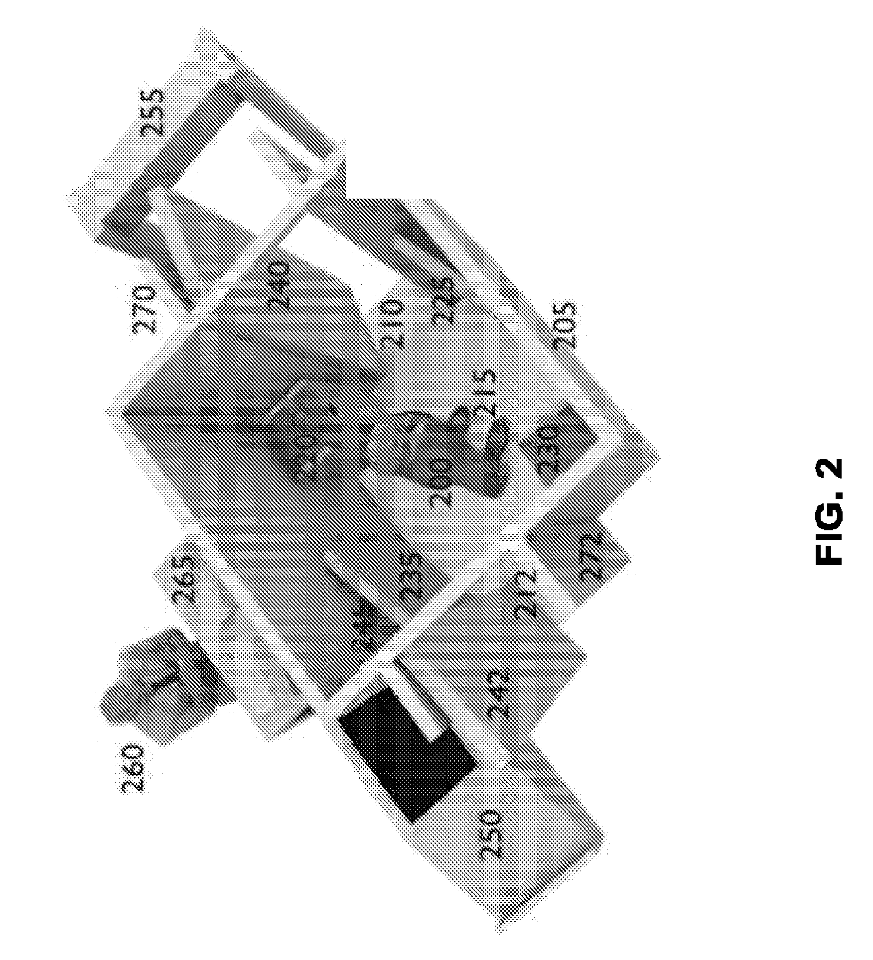
  • Millimeter Wave Concealed Object Detection System Using Portal Deployment
  • Millimeter Wave Concealed Object Detection System Using Portal Deployment
  • Millimeter Wave Concealed Object Detection System Using Portal Deployment

Examples


Embodiment Construction

[0018]Reference will now be made in detail to the preferred embodiments of the present invention, examples of which are illustrated in the accompanying drawings.

[0019]The disclosed system is an approach for deploying a concealed object detection system using pre-engineered and pre-manufactured components to effectively control the deployment surroundings and provide a known environment in which the equipment can operate. The system provides inherent background / peripheral motion and optical clutter mitigation by virtue of its booth-like design. The system can additionally include x-ray baggage machines, iris scanners, biometrics, finger readers, palm readers, metal detectors, backscatter x-ray, nuclear quadrupole resonance, explosives-trace detectors (“sniffers”), and access control cards.

[0020]Embodiments of the system can further allow for a realization of manufacturing, engineering and procurement cost savings due to economies of scale. Furthermore, the system can provides an easy...


PUM


Abstract

A concealed object detection system using pre-engineered and pre-manufactured components to effectively control the deployment surroundings and provide a known environment in which the equipment can operate. The system provides inherent background / peripheral motion and optical clutter mitigation by virtue of its booth-like design. The system can additionally include x-ray baggage machines, iris scanners, biometrics, finger readers, palm readers, metal detectors, backscatter x-ray, nuclear quadrupole resonance, explosives-trace detectors (“sniffers”), and access control cards.

Description

[0001]This Application claims the benefit of U.S. Provisional Application No. 61 / 028,537, filed Feb. 14, 2008. This application is related to U.S. application Ser. No. 10 / 618,950, filed Jul. 14, 2003, U.S. application Ser. No. 12 / 110,520 and U.S. application Ser. No. 12 / 136,000 filed Jun. 9, 2008. Each of these applications is herein incorporated in its entirety by reference.[0002]This application includes material which is subject to copyright protection. The copyright owner has no objection to the facsimile reproduction by anyone of the patent disclosure, as it appears in the Patent and Trademark Office files or records, but otherwise reserves all copyright rights whatsoever.FIELD OF THE INVENTION[0003]The present invention relates in general to the field of concealed object detection, and in particular to deployment systems for millimeter wave concealed object detection systems.BACKGROUND OF THE INVENTION[0004]Containerized access control systems are known in the art for providin...

Claims


Application Information

Patent Timeline
IPC IPC(8): H04N5/30
CPCG01S13/887
Inventor DALY, ROBERT PATRICKREINPOLDT, III, WILLEM H.
Owner MICROSEMI
Learn More