
System for seat-actuated head rest extension and retraction

a head rest and seat technology, applied in the field of seat-actuated head rests, can solve the problems of increased fixed height, increased effort, and inability to meet the needs of passengers, and achieve the effects of reducing the development cycle, high travel distance, and low effor

Active Publication Date: 2011-05-05
FORD GLOBAL TECH LLC
View PDF20 Cites 18 Cited by
  • Summary
  • Abstract
  • Description
  • Claims
  • Application Information

AI Technical Summary

Benefits of technology

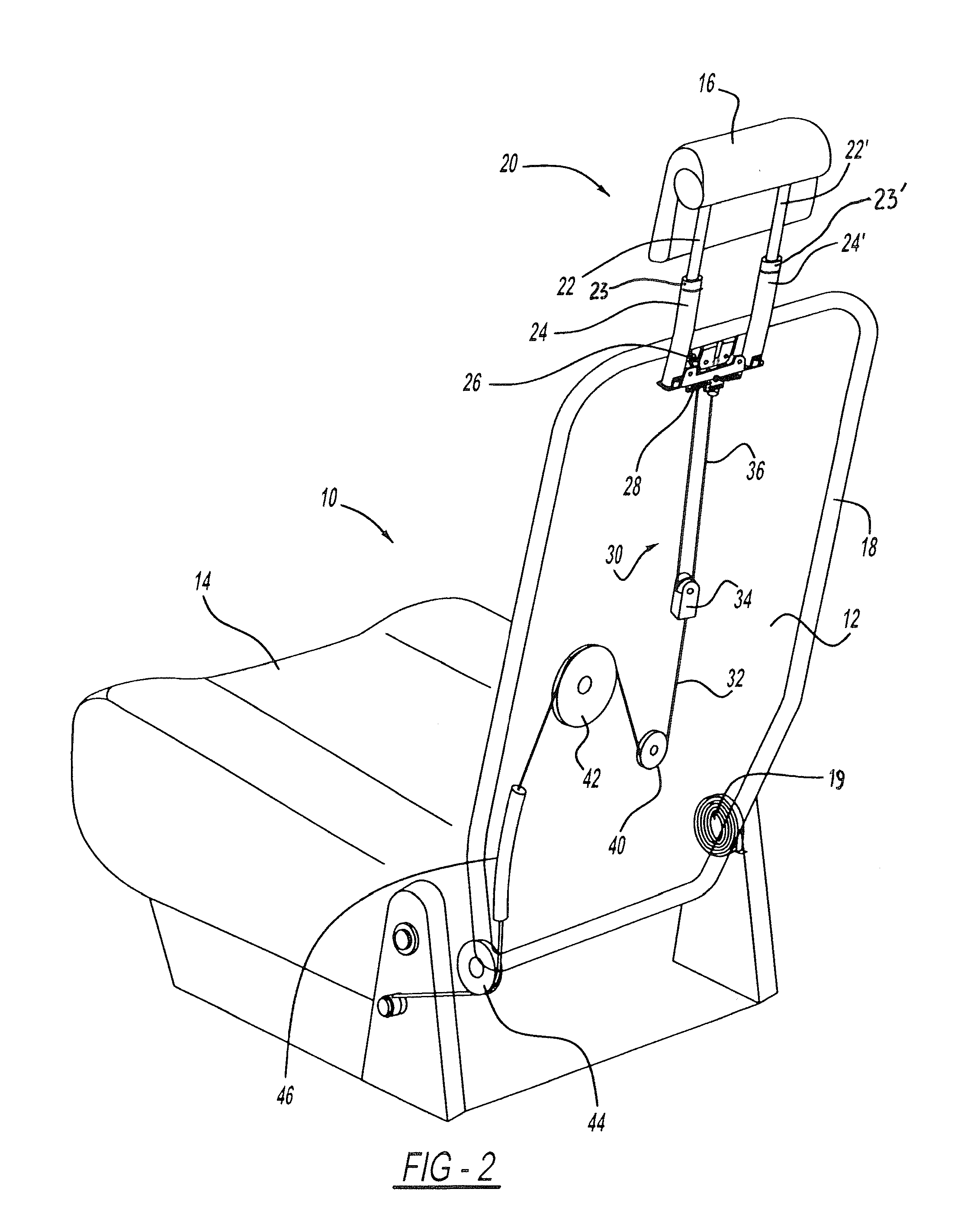
[0009]A cable is provided. One end of the cable is operatively associated with the latching assembly and at the other end is attached to the seat base. A series of pulleys restrain the cable and guide its operation.
[0011]Accordingly, the disclosed invention provides an improvement over known arrangements by providing the CF springs to provide high travel distances combined with low efforts. Other advantages provided by the disclosed invention are that the mechanism is contained entirely in the seat back and thus seat appearance is unchanged, the other existing seat mechanisms are unaffected reducing the development cycle and reducing the amount of revalidation testing, the extension and retraction functions are automatically synchronized with the movement of the seat back so that the user does not have to take additional steps, the mechanism is simple and cost effective, uses existing seat concepts in a new and unique way, and the arrangement may be easily adapted to operate as a powered system.

Problems solved by technology

Frequently, however, the seat occupant incorrectly adjusts the height of the headrest, often making the position choice for reasons of comfort only.
Often the head rest interferes with proper movement of the seat back from its upright position to its lowered position when the operator is arranging the seat for package storage.
The lowered position may not be optimum for passenger safety.
A further complication relates to the anticipated requirement for taller head rest positions than current products can provide.
However, this greater fixed height often precludes existing seat designs from other functions such as the above-described seat back lowering for use in storing packages, or an inability to meet the height requirement without relying on the customer to adjust the position of the head rest.
Known systems are not capable of simultaneously achieving both the height degree anticipated to be required for proper operation of a seat assembly and the capability of moving from an upright position to a lowered position.

Method used


Image

  • System for seat-actuated head rest extension and retraction
  • System for seat-actuated head rest extension and retraction
  • System for seat-actuated head rest extension and retraction

Examples


Embodiment Construction

[0021]In the following figures, the same reference numerals are used to refer to the same components. In the following description, various operating parameters and components are described for one constructed embodiment. These specific parameters and components are included as examples and are not meant to be limiting.

[0022]With reference to FIG. 1, a side view of a seat assembly of the disclosed invention is shown and is generally illustrated as 10. The seat assembly 10 includes a seat back 12 and a seat base 14. Attached to the seat back 12 is a movable head rest 16. The head rest 16 is movable between an extended position when the seat back 12 is in its upright position (as illustrated in solid lines) and a retracted position when the seat back 12 is moved to its lowered position (such downward movement being illustrated in broken lines).

[0023]FIG. 2 illustrates a perspective view of the seat assembly 10 with the seat back 12 in its upright position. The covering of the seat bac...


PUM


Abstract

A head rest system for an automotive vehicle seat movable between an extended position when the seat back of the vehicle seat is in its upright position and a retracted position when the seat back is in its lowered position. The system includes a seat base, a seat back pivotably attached to the seat base, a head rest movably attached to the seat back by a head rest attachment assembly, and a head rest movement balancing portion. The head rest attachment assembly includes a fixed portion attached to the seat back and a movable portion. The fixed portion includes a spool assembly. The movable portion includes a pair of spaced apart posts attached to the underside of the head rest and a latching assembly. The spaced apart posts are slidably attached to the fixed portion. The head rest movement balancing portion includes a pair of spaced apart constant force springs. Each of the springs has a spool attachment end and a latching assembly attachment end. A cable is provided. One end of the cable is operatively associated with the latching assembly and at the other end is attached to the seat base. A series of pulleys restrain the cable and guide its operation. The disclosed system fixes the head rest at the required height, prevents the passenger from adjusting the head rest when the seat is in an occupiable position, and retracts the head rest automatically when the seat back is folded thereby providing sufficient clearances.

Description

TECHNICAL FIELD[0001]The disclosed invention relates generally to automotive head rests. More particularly, the disclosed invention relates to automotive head rests that extend and retract on selective movement of the seat back.BACKGROUND OF THE INVENTION[0002]Seat head rests have been used for many years in automotive vehicles. These head rests generally extend vertically from the seat back and may prevent neck hyperextension. For optimum effectiveness, such head rests must be adjusted properly. Frequently, however, the seat occupant incorrectly adjusts the height of the headrest, often making the position choice for reasons of comfort only.[0003]Complicating the proper positioning of the head rest relative to the seat back is the fact that many automotive vehicles today are configured so that one or more seat backs may be folded flat or relatively flat against the seat base, thereby allowing the back of the seat back to be used as storage space for packages. Often the head rest in...

Claims


Application Information

Patent Timeline
Patent Type & Authority Applications(United States)
IPC IPC(8): B60N2/48B60N2/20
CPCB60N2/20B60N2/4832B60N2/4811B60N2/832B60N2/812
Inventor JENSEN, MATTHEW T.
Owner FORD GLOBAL TECH LLC
Learn More