
Control unit and method for controlling the supply of a vehicle with multiple fuels

a technology of control unit and fuel supply, which is applied in the direction of electrical control, process and machine control, instruments, etc., can solve the problems of jet fuel no longer being able to be obtained and used at acceptable prices or in sufficient quantities, and unavoidable alternative fuels will find their way into aviation, so as to achieve favorable energy and weight balan

Inactive Publication Date: 2011-05-05
AIRBUS OPERATIONS GMBH
View PDF4 Cites 26 Cited by
  • Summary
  • Abstract
  • Description
  • Claims
  • Application Information

AI Technical Summary

Benefits of technology

[0018]f) In addition, an optimization parameter may be provided for minimizing a fuel consumption for the entire mission.
[0019]g) Furthermore, an optimization parameter may be oriented to a maximization of the range which may be implemented using the vehicle. The ratio of the fuel mass flows may be selected, for example, so that in longer operational phases, for example, during cruising of an aircraft, the fuel which is carried along and which has a higher specific weight is used first as much is possible, in order to cause energy savings because of the more rapid reduction of the vehicle mass and thus an increase of the range
[0026]In a first procedure, a ratio of first fuel mass flow to second fuel mass flow may be set, which permits the simultaneous use of both fuel types in a mixing ratio, for example, during a transition between two operational phases or during a holding flight, for example, to lengthen the possible flight time. In another procedure, one fuel type or the other fuel type is used exclusively, depending on the respective operational phase and the optimization parameters.
[0028]Furthermore, the control unit according to the invention is adapted for receiving data about the available mass of first fuel and second fuel and information about the mass-specific energy and / or its caloric value via a data input module or the like. The control unit according to the invention is made capable therefrom of supplying the power plants with a required fuel flow, which results in sufficient provision of thrust energy by the internal combustion engine. The control unit according to the invention may deliver the first fuel or the second fuel alternatively or in parallel to one another to the internal combustion engine.
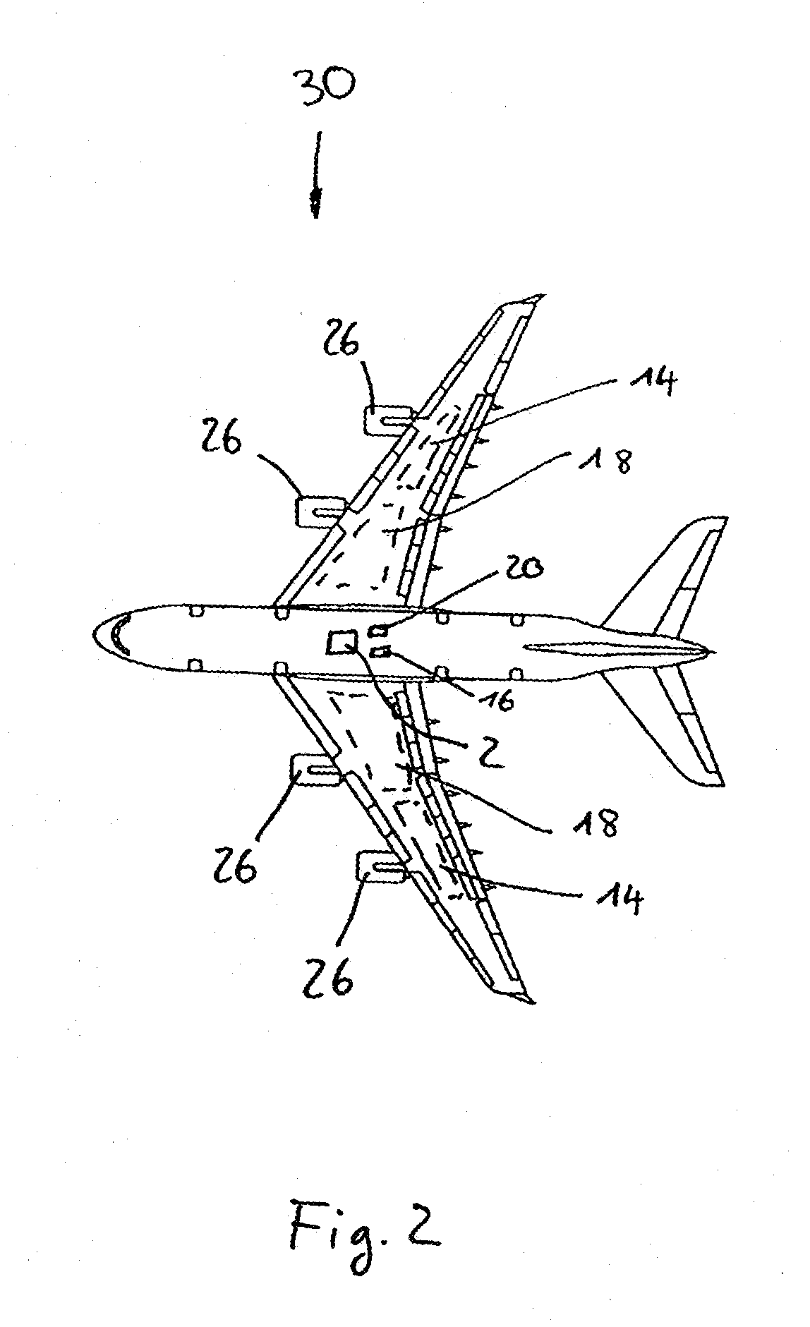
[0032]The control unit according to the invention is responsible in this configuration for maximizing a range, accordingly considering permitted and non-permitted fuels for specific flight phases, and reacting to infrastructure conditions at various destination airports. An aircraft may thus be provided which allows performance-optimized operation with respect to the use of different fuel types.
[0040]A consideration of an electrical drive which is usable in parallel or sequentially in the actual optimization of the use of two different fuel types would also be advantageous. A particularly favorable energy and weight balance may be achieved for established mission phases.

Problems solved by technology

However, it is obvious that existing fossil resources are inherently restricted, so that it must be expected that in future fuels such as jet fuel will no longer be able to be obtained and used at acceptable prices or in sufficient quantities.
As a result of this development, it is unavoidable that alternative fuels will find their way into aviation.
However, until such alternative fuels may be extensively provided, it is to be expected that multiple types of fuel will only be able to be provided in varying quantities at various locations worldwide, namely fuels based on hydrocarbons and alternative, future fuels.
On the system side, an application of two different fuels for all power plants used was not possible in any of the experimental power plants without prior retrofitting or the like.

Method used


Image

  • Control unit and method for controlling the supply of a vehicle with multiple fuels
  • Control unit and method for controlling the supply of a vehicle with multiple fuels
  • Control unit and method for controlling the supply of a vehicle with multiple fuels

Examples


Embodiment Construction

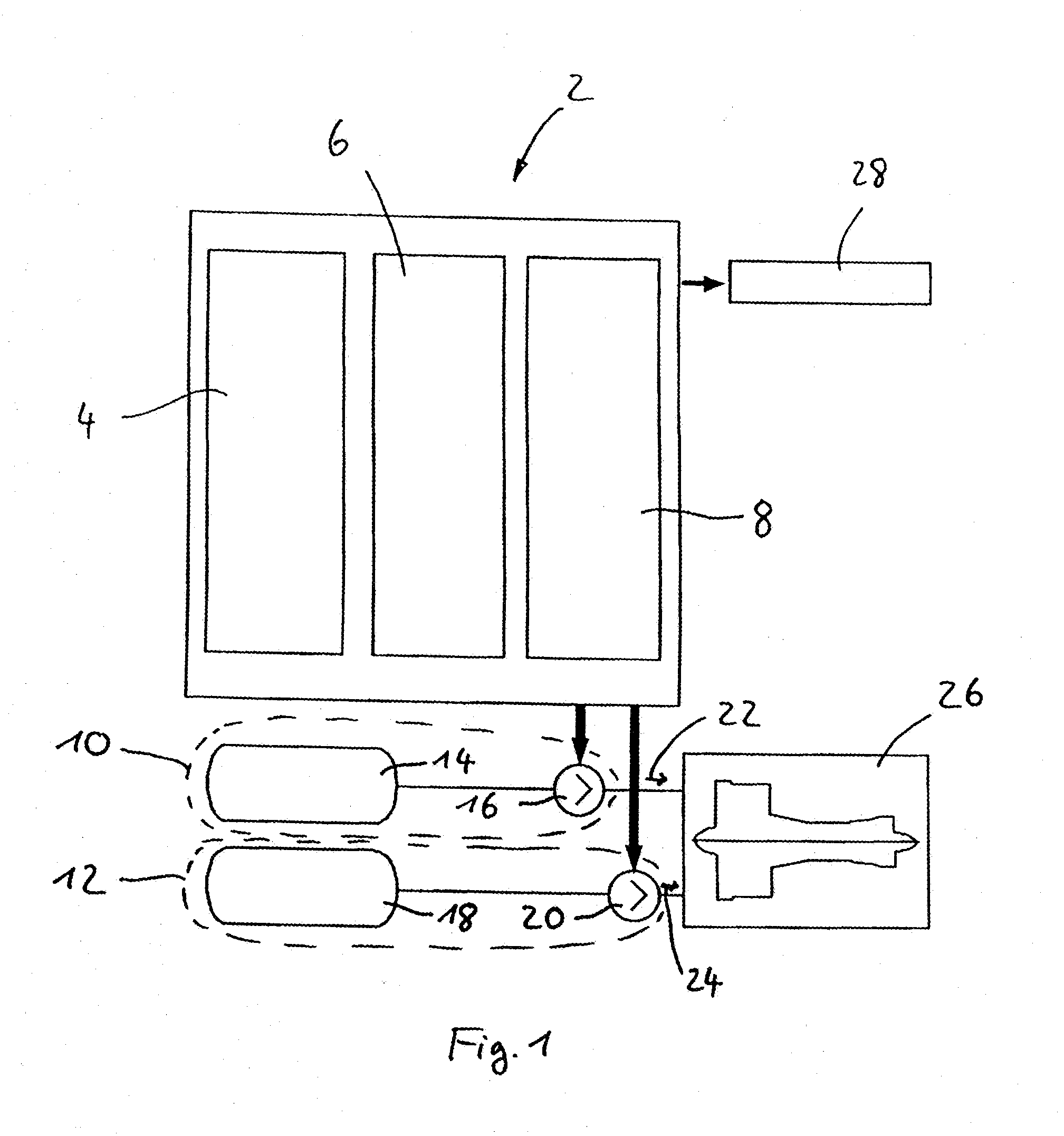
[0047]FIG. 1 schematically shows a control unit 2 according to the invention, which is equipped with an input means 4 and a computing unit 6. The input means 4 is adapted for acquiring numerous data and providing them for further processing. Stored data may be saved in a storage unit 8.

[0048]The control unit 2 according to the invention is connected to a first supply apparatus 10 and a second supply apparatus 12, the first supply apparatus 10 having a first fuel tank 14 and a first injection pump 16 and the second supply apparatus 12 having a second fuel tank 18 and a second injection pump 20.

[0049]The control unit 2 is thus capable, by activating the first supply apparatus 10 and the second supply apparatus 12, of conducting a first mass flow 12 and a second mass flow 24 to an internal combustion engine 26. Only a single power plant is shown as the internal combustion engine 26 here as an example, of course, however, it is obvious that multiple power plants may be connected to the ...


PUM


Abstract

A control unit for controlling the supply of a vehicle having at least one internal combustion engine with multiple fuels has at least one input means for supplying optimization parameters, fuel parameters, and operational data, at least one storage unit for storing the optimization parameters, the fuel parameters, and the operational data, and at least one computing unit. The control unit is adapted for being connected to at least one first supply apparatus for supplying a first fuel to the internal combustion engine and to at least one second supply apparatus for supplying a second fuel to the internal combustion engine, and of controlling a first mass flow of supplied first fuel and a second mass flow of supplied second fuel. The computing unit optimizes the ratio of first mass flow and second mass flow for all operational phases of the vehicle to fulfill the specified optimization parameters.

Description

CROSS-REFERENCE TO RELATED APPLICATIONS[0001]This application claims the benefit of the filing date of U.S. Provisional Patent Application No. 61 / 258,281 filed Nov. 5, 2009, the disclosure of which application is hereby incorporated herein by reference.BACKGROUND OF THE INVENTION[0002]The invention relates to a control unit for controlling the supply of a vehicle with multiple fuels, a method for controlling the supply of a vehicle with multiple fuels, and an aircraft, which is adapted for being operable with multiple fuels.[0003]Conventional fuels based on hydrocarbon, such as jet fuel, currently represent the backbone of fuel supply in aviation. However, it is obvious that existing fossil resources are inherently restricted, so that it must be expected that in future fuels such as jet fuel will no longer be able to be obtained and used at acceptable prices or in sufficient quantities. As a result of this development, it is unavoidable that alternative fuels will find their way int...

Claims


Application Information

Patent Timeline
Patent Type & Authority Applications(United States)
IPC IPC(8): B64D37/00F02D19/08
CPCF02C9/40Y02T10/36F02D41/021F02D41/0025Y02T10/30
Inventor SCHWARZE, MALTEWESTENBERGER, ANDREAS
Owner AIRBUS OPERATIONS GMBH
Learn More