
Solar battery module and method for manufacturing the same

a solar battery and module technology, applied in the direction of printed circuit aspects, pv power plants, chemical instruments and processes, etc., can solve the problems of low production efficiency, low thermal stability of inexpensive materials, and high cost of glass-epoxy base plates and polyimide films used for these wiring boards. achieve the effect of preventing positional dislocation

Active Publication Date: 2011-04-28
SHARP KK
View PDF18 Cites 18 Cited by
  • Summary
  • Abstract
  • Description
  • Claims
  • Application Information

AI Technical Summary

Benefits of technology

The present invention provides a solar battery module and a method for manufacturing the same that allows for the design of electrodes at a fine pitch and show a high solar battery characteristic even in a structure in which the solar battery cells are connected by means of a wiring board that is formed of various resin materials whose thermal shrinkages are not sufficiently low. The invention also provides a wiring board that is formed of a resin film that is manufactured by a biaxial stretch method and has a small thermal shrinkage in the direction of the wiring pattern. The invention also provides a solar battery module that uses a direction that has a small design margin as the TD direction, so as to obtain a wiring pattern that is not subjected to the influence of thermal shrinkage. The invention also provides a method for manufacturing the solar battery module using a resin material that is inexpensive and mass-producible. The invention also provides a solar battery module that uses a polyester-related film or a polyester-related film containing polyethylene terephtalate or polyethylene naphthalate.

Problems solved by technology

However, the glass-epoxy base plate and the polyimide film used for these wiring boards are very expensive because they require 1 m2 or more per unit as a material for a solar battery cell module, which is a major cause of the fact that the mass-production is not performed.
To avoid this, there is an idea to use an inexpensive material; however, an inexpensive material generally has a problem with thermal stability.

Method used


Image

  • Solar battery module and method for manufacturing the same
  • Solar battery module and method for manufacturing the same
  • Solar battery module and method for manufacturing the same

Examples


examples

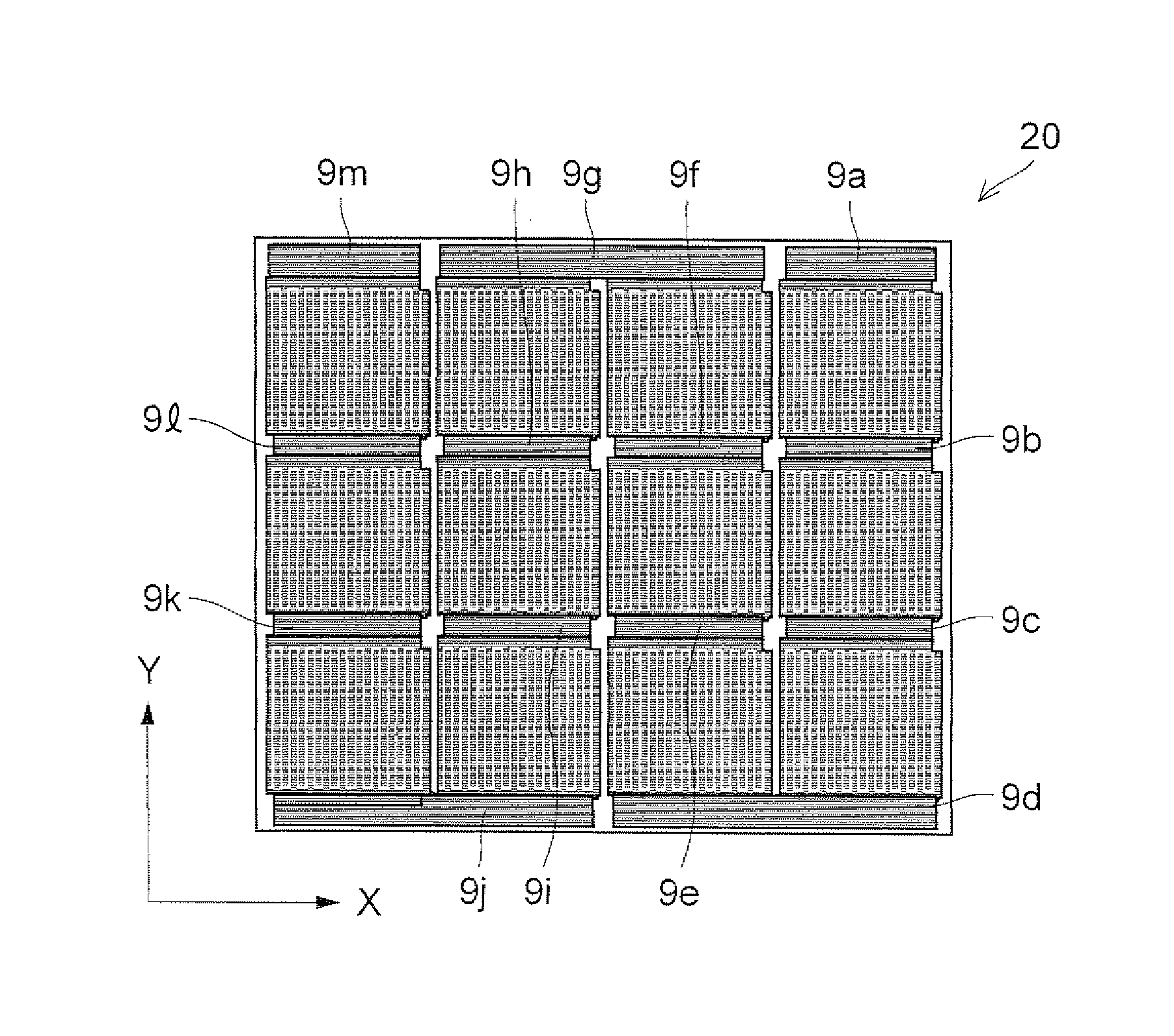
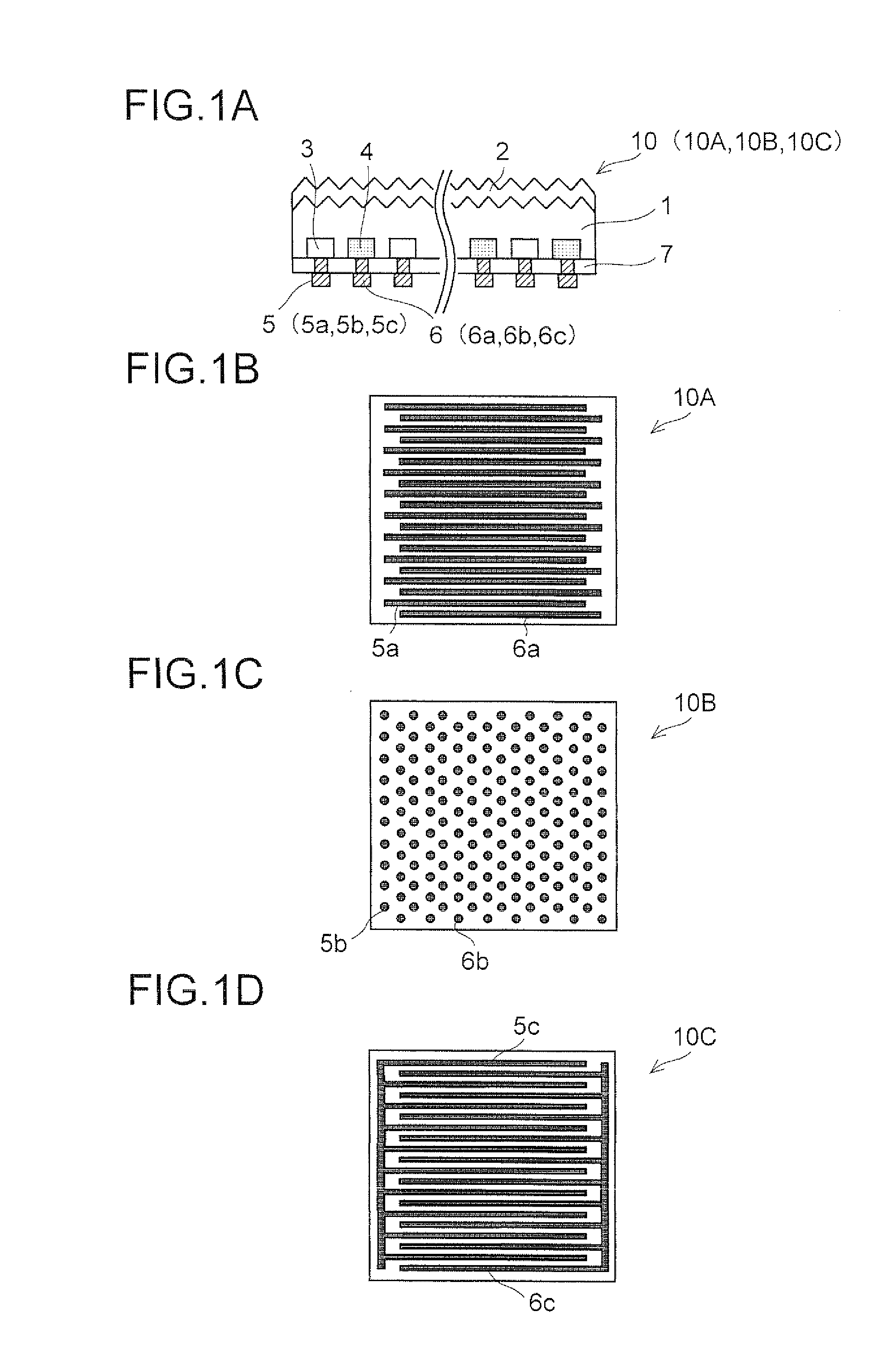
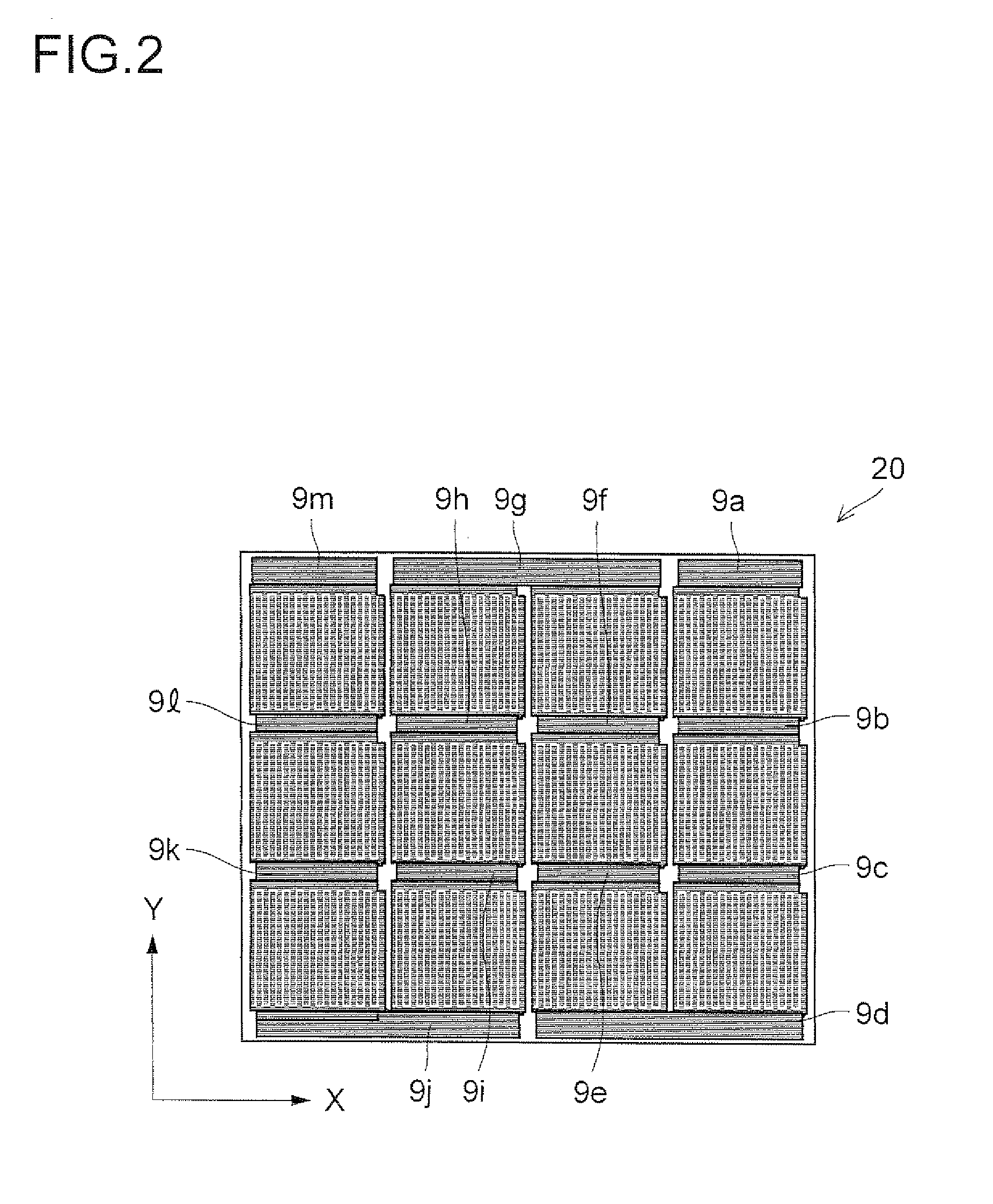
[0053]As examples, a solar battery module M is fabricated by means of; the solar battery cell 10A on which the linear-shape electrode pattern shown in FIG. 1 is formed; and the wiring board 20 shown in FIG. 2. As for the solar battery cell 10A, as shown in FIG. 1(a), the N+ layer 3 and the P+ layer 4 are alternately formed on the back surface of the solar battery; the reflection protective film 2 including, for example, a nitride silicon film is formed on the light receiving surface, and the passivation film 7 is formed on the back surface; the N electrode 5 and the P electrode 6 are formed on the N+ layer and the P+ layer, respectively. It is possible to fabricate the solar battery cell 10A having this structure by means of a known method. Here, the solar battery cell 10A is a baked electrode that contains silver as a main component; the linear-shape N electrode 5a and the P electrode 6a are alternately formed, and the distance between the N electrode 5a and the P electrode 6a is s...


PUM

PropertyMeasurementUnit
temperatureaaaaaaaaaa
melting pointaaaaaaaaaa

Abstract

Provided is a solar battery module wherein solar battery cells are electrically connected to each other by using a wiring board having a predetermined wiring pattern formed on a resin base material. A method for manufacturing such solar battery module is also provided. In the wiring board of the solar battery module, a direction wherein a design margin is small is permitted to be a direction wherein the thermal contraction ratio of the resin base material is small, by the shape of an electrode pattern on the solar battery cell and that of the wiring pattern on the wiring board. At the time of manufacturing such solar battery module, temperature in a heat treatment step is set at 100° C. or higher but not higher than 180° C. Electrode designing at a fine pitch is made possible and the solar battery module exhibits high solar battery characteristics, even when the solar battery cells are connected by using wiring boards composed of various types of resin materials having thermal compression ratio not sufficiently low.

Description

TECHNICAL FIELD [0001]The present invention relates to a solar battery module and a method for manufacturing the same that are able to use a wiring board which is formed of various resin materials.BACKGROUND ART [0002]In recent years, because of global environmental problems such as depletion of energy sources, increase in carbon dioxide in the atmosphere and the like, a clean energy source is desired to be developed, especially, photovoltaic power generation that uses solar battery cells is developed as a new energy source, put into practical use and is on the way of development. As for the solar battery cell, conventionally, the mainstream is a solar battery module that has a structure in which on a light receiving surface of a monocrystalline or polycrystalline-electroconductive-type silicon substrate, a pn junction is formed by diffusing reverse electroconductive-type impurities; and a plurality of solar battery cells, in each of which electrodes are formed on the light receivin...

Claims


Application Information

Patent Timeline
Patent Type & Authority Applications(United States)
IPC IPC(8): H01L31/05H01L31/18
CPCB32B17/10018B32B17/10788B32B17/10871H01L31/02013H01L31/022441H02S40/34H05K1/189H05K3/284H05K2201/0145H05K2201/10143Y02E10/52H01L31/0516Y02E10/50
Inventor FUNAKOSHI, YASUSHI
Owner SHARP KK
Learn More