
Solder pad structure for printed circuit boards and fabrication method thereof

a printed circuit board and solder pad technology, applied in the direction of railway components, synthetic resin layered products, nuclear engineering, etc., can solve the problems of reduced yield of solder paste printing process, undercut defects, and huge technical gap between semiconductor and packaging, and achieve the effect of improving the solder pad structur

Active Publication Date: 2011-04-21
UNIMICRON TECH CORP
View PDF5 Cites 15 Cited by
  • Summary
  • Abstract
  • Description
  • Claims
  • Application Information

AI Technical Summary

Problems solved by technology

A huge technical gap exists between semiconductor and packaging.
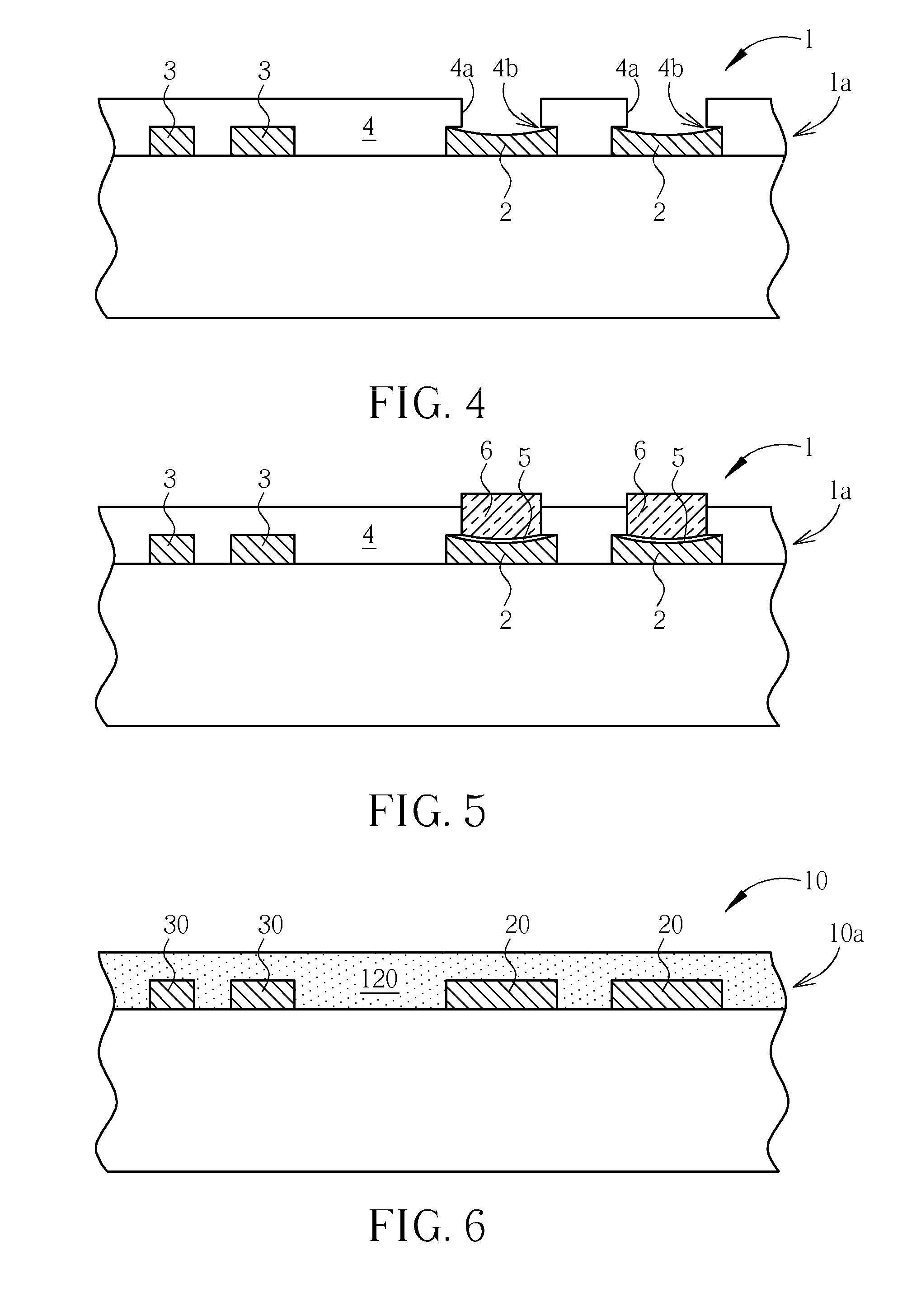
However, this cleaning process results in undercut defects 4b at the bottom of the solder resist openings 4a.
However, the above-described prior art method has several drawbacks.
First, the yield of the solder paste printing process reduces as the pitch between the solder pad structures 2 on the flip-chip side of the circuit board becomes smaller and smaller.
Second, the adhesion of solder paste 6 to the solder resist layer 4 is poor.
Third, the undercut defects 4b formed during the chemical micro-etching and cleaning process create high stress points in the subsequent processes leading to reliability problems of the circuit board.

Method used


Image

  • Solder pad structure for printed circuit boards and fabrication method thereof
  • Solder pad structure for printed circuit boards and fabrication method thereof
  • Solder pad structure for printed circuit boards and fabrication method thereof

Examples


Embodiment Construction

[0020]FIG. 6 to FIG. 9 are schematic, cross-sectional diagrams showing a method for fabricating a solder pad structure on a circuit board in accordance with one preferred embodiment of this invention. First, as shown in FIG. 6, a surface wiring structure 10a is provided on the surface of the circuit board 10. The surface wiring structure 10a may include but not limited to a plurality of copper pad structure 20 and fine traces 30. It is to be understood that the circuit board 10 may be a single wiring layer circuit board, double wiring layer circuit board or multiple wiring layer circuit board. For the sake of simplicity, the conductive via holes or other inner layer interconnection inside the circuit board 10 are not shown in the figures.

[0021]After the formation of the surface wiring structure 10a, a non-conductive material layer 120 is coated on the surface of the circuit board 10. The non-conductive material layer 120 comprises a dielectric matrix and laser-activable catalytic pa...


PUM

PropertyMeasurementUnit
sizeaaaaaaaaaa
thicknessaaaaaaaaaa
thicknessaaaaaaaaaa

Abstract

A method for fabricating a solder pad structure. A circuit board having thereon at least one copper pad is provided. A solder resist is formed on the circuit board and covers the copper pad. A solder resist opening, which exposes a portion of the copper pad, is formed in the solder resist by laser. The laser also creates a laser activated layer on sidewalls of the solder resist opening. A chemical copper layer is then grown from the exposed copper pad and concurrently from the laser activated layer.

Description

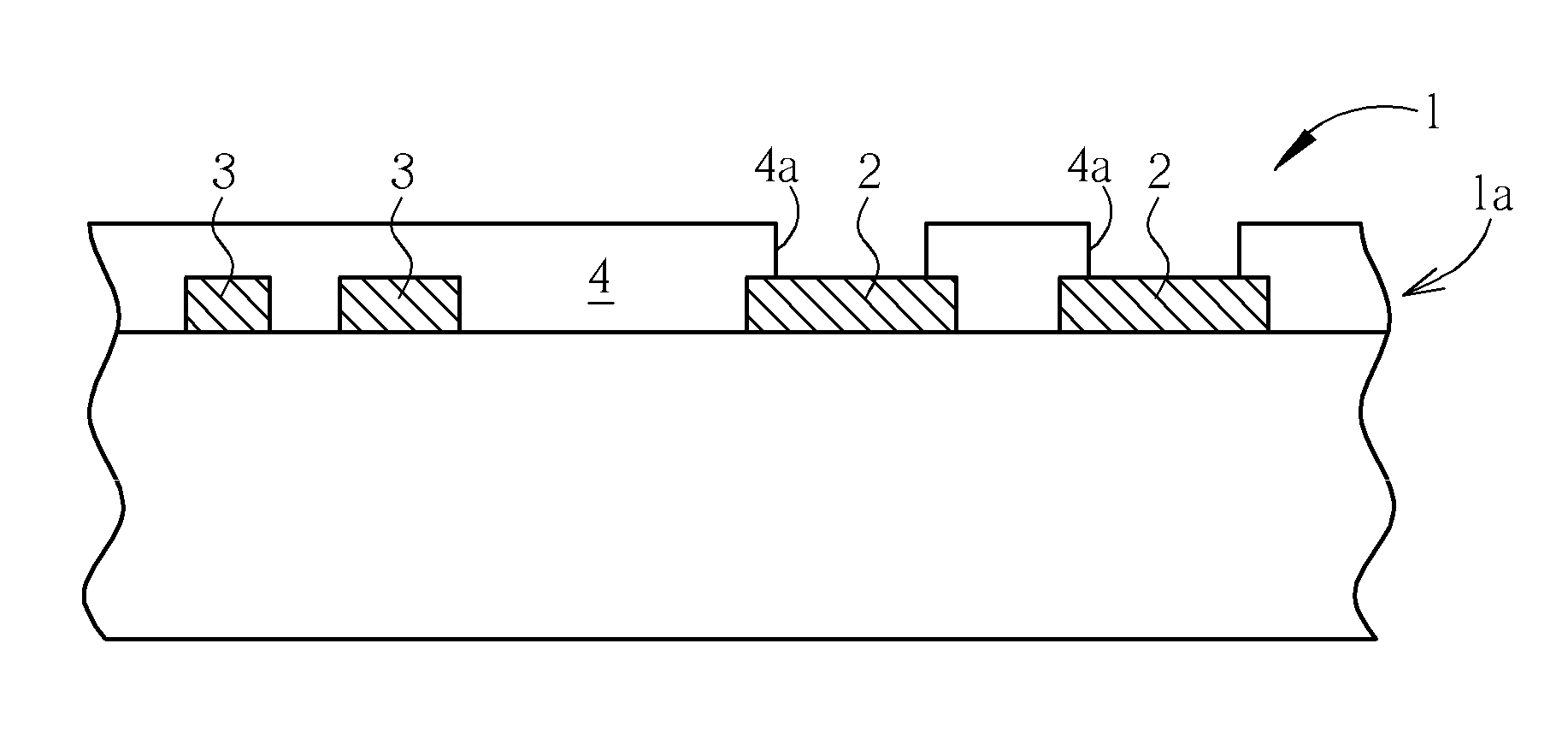
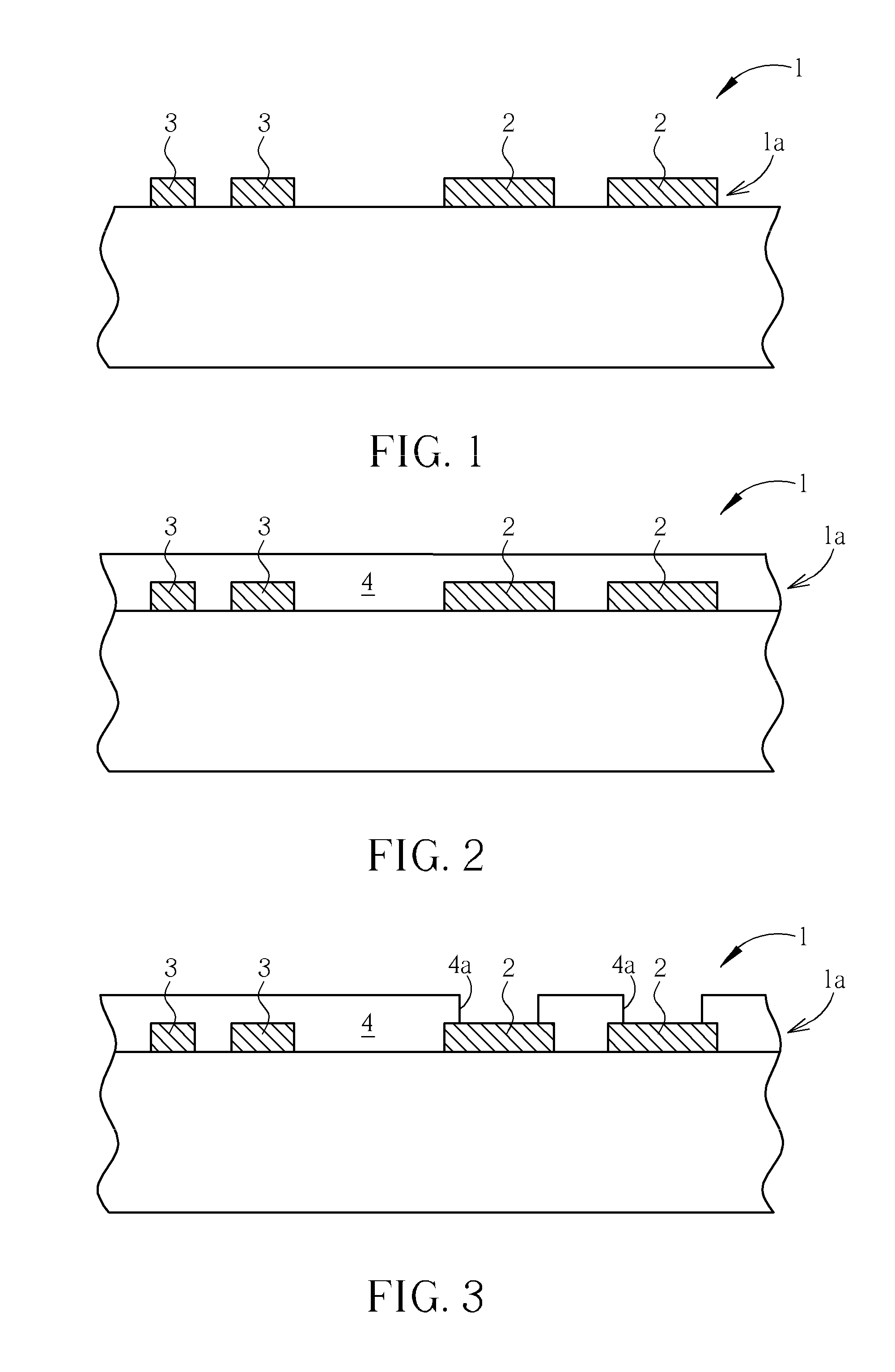
BACKGROUND OF THE INVENTION[0001]1. Field of the Invention[0002]The present invention relates generally to the fabrication of circuit boards. More particularly, the present invention relates to a solder pad structure for printed circuit boards and fabrication method thereof.[0003]2. Description of the Prior Art[0004]Rapid changes in the semiconductor industry will continue toward higher functionality that leads to higher I / O counts, pushing packaging towards new, smaller, and higher density architectures. The semiconductor industry has developed features of 30 nm for high performance microprocessors. However, the feature size that the packaging industry can produce is about 15˜20 μm. A huge technical gap exists between semiconductor and packaging. In order to keep pace with semiconductor process development, a process for finer pitch wiring substrate is necessary.[0005]FIG. 1 to FIG. 5 demonstrate a conventional solder resist process and the solder paste printing process after the s...

Claims


Application Information

Patent Timeline
Patent Type & Authority Applications(United States)
IPC IPC(8): B32B15/00B05D5/12
CPCB32B15/08Y10T29/49124H05K3/0035H05K3/185H05K3/285H05K3/4007H05K3/421H05K3/422H05K2201/0236H05K2201/0367H05K2203/0191H05K2203/0565H05K2203/1415Y10T29/49144Y10T29/49165Y10T29/49149Y10T428/24917B32B15/20B32B7/06B32B27/06B32B27/36B32B2255/00B32B2255/10B32B2255/205B32B2255/28B32B2264/105B32B2307/204B32B2307/40B32B2307/748B32B2457/08
Inventor TSENG, TZYY-JANGCHIANG, SHU-SHENG
Owner UNIMICRON TECH CORP
Learn More