
In-line forward/backward fiber-optic signal analyzer

Active Publication Date: 2011-04-21
LOCKHEED MARTIN CORP
View PDF36 Cites 64 Cited by
  • Summary
  • Abstract
  • Description
  • Claims
  • Application Information

AI Technical Summary

Benefits of technology

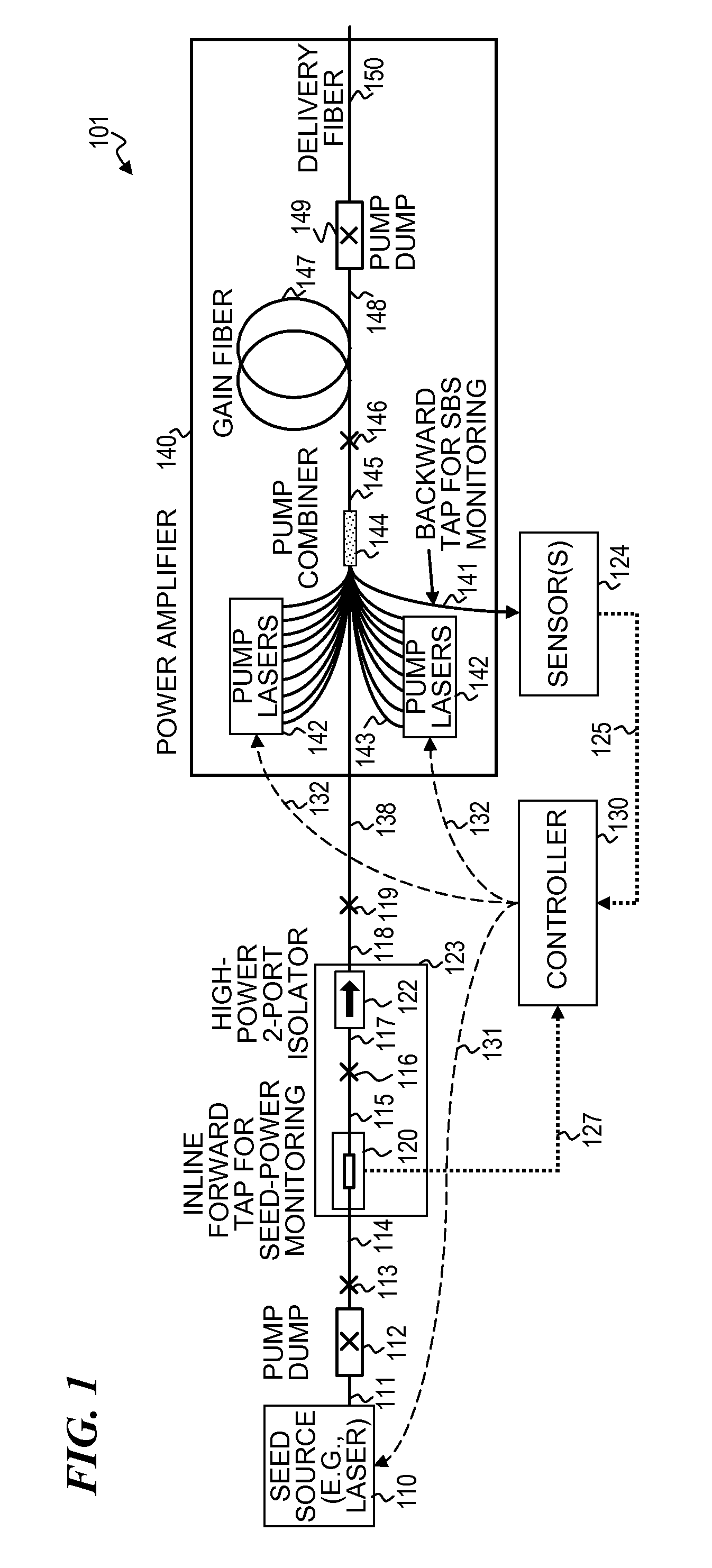
[0035]In some embodiments, the tapping and sensing provide a measurement of the forward-propagating signal that indicates the health of the optical-signal source (e.g., the seed laser and / or optical-amplification stages in some embodiments) that precedes the measurement point (i.e., the upstream parts of the system that generate the forward-propagating signal). In some embodiments, one or more power-level measurements of the forward-propagating signal are used in a feedback loop to maintain the forward signal's power level at a desired (e.g., constant) value. In the case of significant reduction (or increase) of the forward signal, the feedback system can turn off the laser system to mitigate any catastrophic damage that might otherwise occur to the amplifier stage(s).

Problems solved by technology

Forward ASE-level measurement may be difficult or not feasible in some laser systems due to lack of access to the high-power laser output (at the output of a downstream optical amplifier).

Method used


Image

  • In-line forward/backward fiber-optic signal analyzer
  • In-line forward/backward fiber-optic signal analyzer
  • In-line forward/backward fiber-optic signal analyzer

Examples


Embodiment Construction

[0051]Although the following detailed description contains many specifics for the purpose of illustration, a person of ordinary skill in the art will appreciate that many variations and alterations to the following details are within the scope of the invention. Accordingly, the following preferred embodiments of the invention are set forth without any loss of generality to, and without imposing limitations upon the claimed invention. Further, in the following detailed description of the preferred embodiments, reference is made to the accompanying drawings that form a part hereof, and in which are shown by way of illustration specific embodiments in which the invention may be practiced. It is understood that other embodiments may be utilized and structural changes may be made without departing from the scope of the present invention.

[0052]The leading digit(s) of reference numbers appearing in the Figures generally corresponds to the Figure number in which that component is first intr...


PUM


Abstract

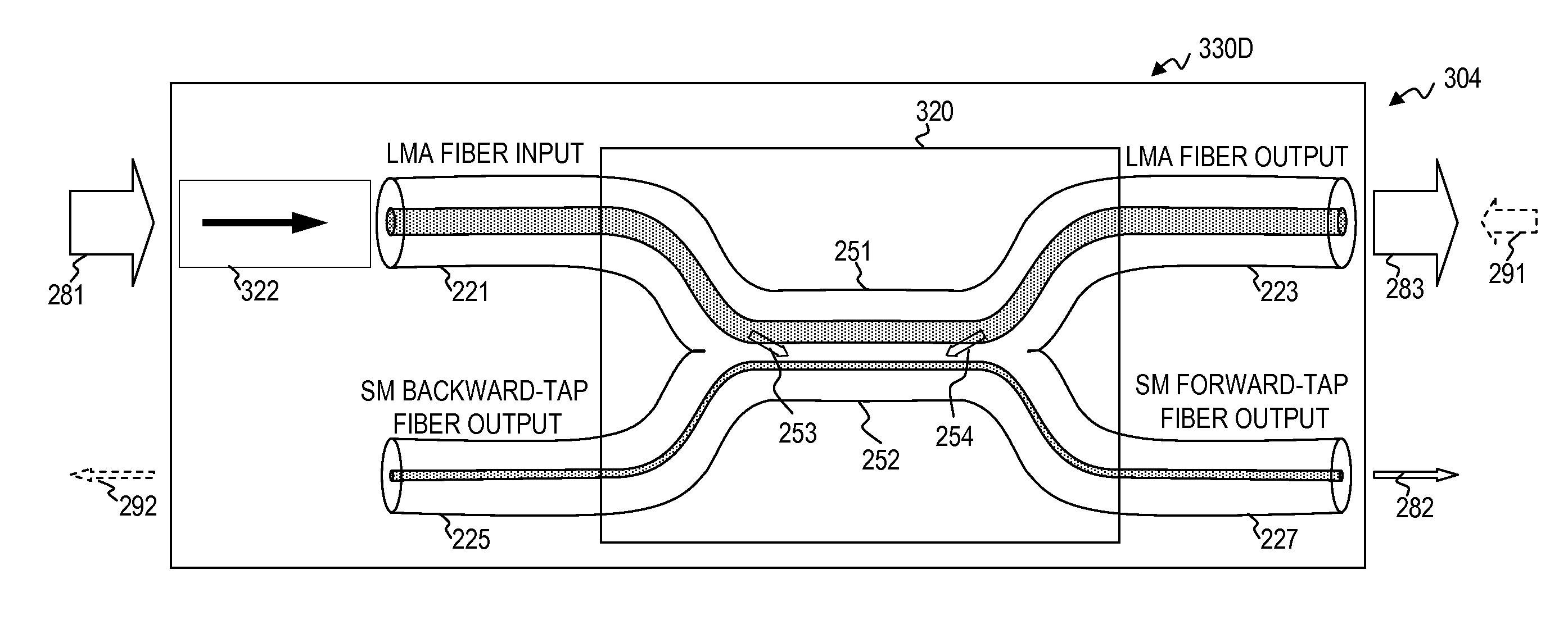
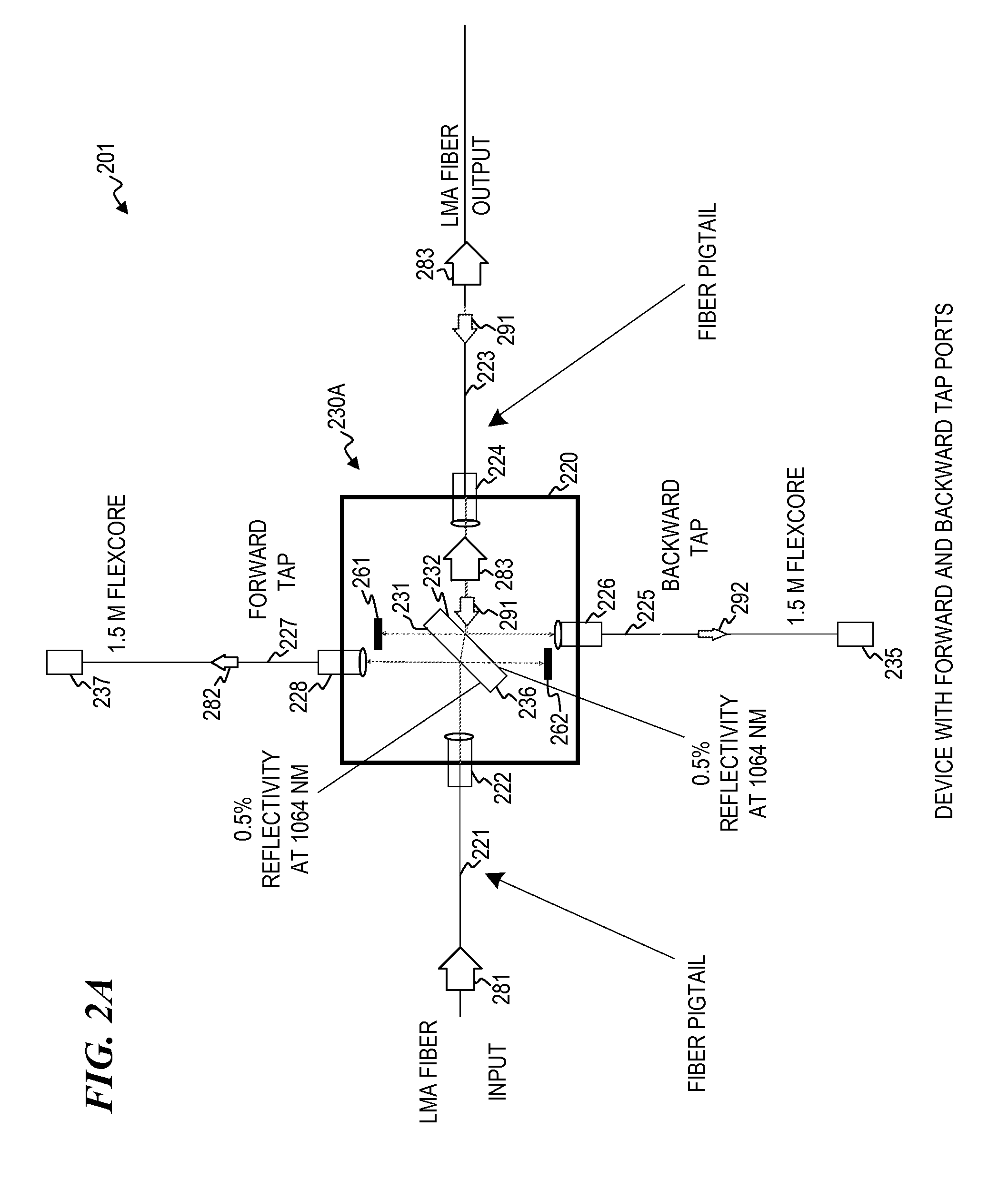
An optical connector having a plurality of directional taps and connecting between a plurality of optical waveguides (e.g., such as a connector between a waveguide that is part of, or leads from, a seed laser and / or an initial optical-gain-fiber power amplifier, and a waveguide that is part of, or leads to, an output optical-gain-fiber power amplifier and / or a delivery fiber), wherein one of the directional taps extracts a small amount of the forward-traveling optical output signal from the seed laser or initial power amplifier (wherein this forward-tapped signal is optionally monitored using a sensor for the forward-tapped signal), and wherein another of the directional taps extracts at least some of any backward-traveling optical signal that may have been reflected (wherein this backward-tapped signal is optionally monitored using a sensor for the backward-tapped signal).

Description

CROSS-REFERENCE TO RELATED APPLICATIONS[0001]This application claims benefit under 35 U.S.C. §119(e) of[0002]U.S. Provisional Patent Application No. 61 / 253,041 filed Oct. 19, 2009, by Tolga Yilmaz et al., titled “Fiber-Pigtailed Isolator with Tap Ports for Forward and Backward Optical Signal Monitoring”;[0003]U.S. Provisional Patent Application No. 61 / 263,736 filed Nov. 23, 2009, by Matthias P. Savage-Leuchs et al., titled “Q-Switched Oscillator Seed-Source for MOPA Laser Illuminator Method and Apparatus” (Attorney Docket 5032.051PV1);[0004]U.S. Provisional Patent Application No. 61 / 343,947 filed Apr. 12, 2010, by Matthias P. Savage-Leuchs, titled “High-Power Laser System having Delivery Fiber with Non-Circular Cross Section for Isolation Against Back Reflections” (Attorney Docket 5032.052PV1);[0005]U.S. Provisional Patent Application No. 61 / 343,948 filed Apr. 12, 2010, by Matthias P. Savage-Leuchs, titled “High Beam Quality and High Average Power from Large-Core-Size Optical-Fiber ...

Claims


Application Information

Patent Timeline
IPC IPC(8): G02B6/26H01S3/09
CPCG02B6/2817G02B6/2835G02B6/4207H01S3/06754H01S3/1301H01S3/094053H01S3/09408H01S3/2308H01S3/094003G02B6/4291G02B6/4287H01S3/13013H01S3/10015H01S2301/02
Inventor YILMAZ, TOLGABRAR, KHUSHLEMAIRE, CHARLES A.
Owner LOCKHEED MARTIN CORP
Learn More