
Buffered Large Core Fiber

Inactive Publication Date: 2011-04-14
CORNING INC
View PDF19 Cites 23 Cited by
  • Summary
  • Abstract
  • Description
  • Claims
  • Application Information

AI Technical Summary

Benefits of technology

[0015]One advantage of the optical fiber according to the present invention is that it has a buffer coating need not be stripped when such a fiber is used in a connector. Another advantage of the optical fiber according to the present invention is that the protective coating minimizes the fiber movement inside the buffer during cleaving and also during subsequent use in connectors, due to strong adhesion of the protective coating to both the cladding and the buffer coating. Yet another advantage of the optical fiber according to the present invention is that the protective coating prevents the optical fiber core from moving off-center during cleaving, thus minimizing coupling losses when this fiber is coupled to another fiber. Yet another advantage of the optical fiber according to the present invention is that the protective coating also provides protection during handling and storage if the final permanent buffer is not applied at the same time as the protective coating.

Problems solved by technology

However, the step of stripping of the buffer layer adds expense and complexity to the connectorization process.
Furthermore, some of the buffer coating may be left in place after the mechanical stripping step, resulting in noncircular / non uniform outer diameter.
If such a fiber is cut or cleaved without removal of the buffer layers, the force of the fiber or the cleaving tool pushes the fiber to move at least partially through the soft layer, so that the fiber is not concentric with the coatings, making it difficult to connect this fiber to another fiber without incurring large insertion loss.
However, a fiber with such a small outer diameter may be difficult to handle and typically requires additional protection for use in typical applications.

Method used


Image

  • Buffered Large Core Fiber
  • Buffered Large Core Fiber

Examples


example 1

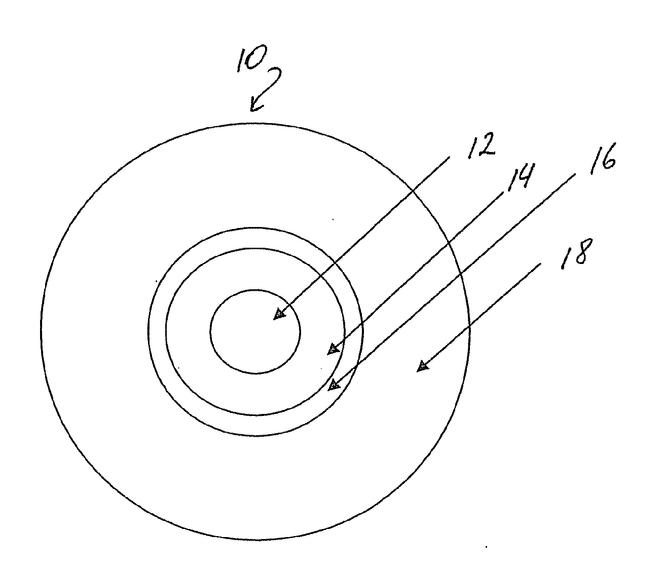
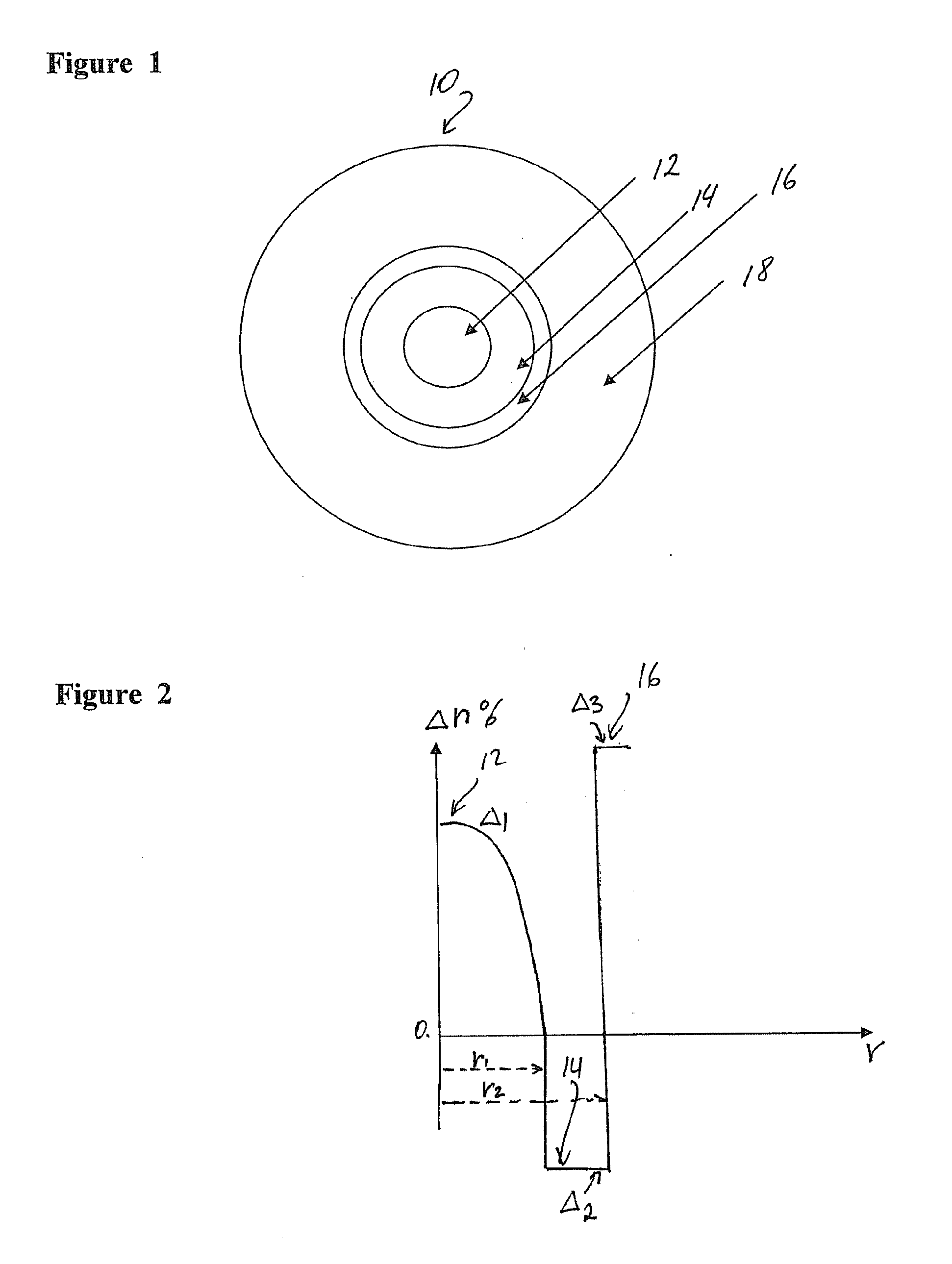
[0030]This exemplary optical fiber comprises: (i) a multi-mode silica based glass core 12; (ii) a cladding 14 surrounding the core 12; (iii) a thin protective coating 16, and (iv) a buffer coating 18 surrounding the protective coating 16. The glass core 12 has an outer diameter 200 μm diameter and an index of refraction n1. It is made of silica glass doped with germanium such that the peak of the graded refractive index of the core (relative to pure silica) is Δ1=1.7%. The cladding thickness is 15 μm. The outer diameter of the cladding 14 in this exemplary fiber is 230 μm. The cladding 14 is made of fluorinated polymer, with a relative refractive index delta Δ2=−3.4% (relative to pure silica). This, the absolute relative refractive index difference between the core and the cladding of this exemplary fiber is 5.1%. The numerical aperture of this exemplary fiber is about 0.46. In this embodiment cladding 14 has the secant modulus at 2.5% strain of 412 MPa. Preferably, the shore D hard...


PUM

PropertyMeasurementUnit
Lengthaaaaaaaaaa
Lengthaaaaaaaaaa
Lengthaaaaaaaaaa

Abstract

An optical fiber comprising: (i) a multi-mode silica based glass core, said core having a 80-300 μm diameter and an index of refraction n1; (ii) a cladding surrounding the core, said cladding having a thickness ≦20 μm and index of refraction index of refraction n2<n1, the cladding comprising (a) fluorine doped silica with relative index of refraction delta <0, or (b) a polymer with relative index of refraction delta <0; (iii) a protective coating, the protective coating having a Young's modulus greater than 700 MPa, a thickness ≦15 μm, and an index of refraction index of refraction n3>n2; and (iv) a permanent buffer.

Description

[0001]This application claims the benefit of priority under 35 USC 119(e) of U.S. Provisional Application Ser. No. 61 / 299,397 filed on Jan. 29, 2010 and U.S. Provisional Application Ser. No. 61 / 250,957 filed Oct. 13, 2009.BACKGROUND[0002]1. Field[0003]The present invention relates generally to optical fibers which include a glass core, a plastic or glass cladding surrounding the core, and a thin protective coating surrounding the cladding, and a protective buffer.[0004]2. Technical Background[0005]Optical fibers with a glass core and glass cladding, a permanent protective coating and a strippable buffer coating are known. The buffer coating is typically includes an inner, soft, resilient layer and an outer, rigid layer. The soft, resilient layer provides the optical fiber element with protection against microbending losses, and the outer, rigid layer protects the underlying layers from abrasion and mechanical damage. When such an optical fiber is connectorized, the buffer layer is s...

Claims


Application Information

Patent Timeline
IPC IPC(8): G02B6/036G02B6/26
CPCC03C3/06C03C25/105C03C25/1065C03C2201/31G02B6/02395G02B6/0281G02B6/0288G02B6/03627G02B6/4402G02B6/02023
Inventor BENJAMIN, SELDON DAVIDBENNETT, KEVIN WALLACEBOHLER, GREGORY BLAKECOON, JEFFREYNAVE, SAMUEL DON
Owner CORNING INC
Learn More