
Tunable Wavelength Illumination System

a wavelength illumination and wavelength technology, applied in the field of illumination systems, can solve the problems of inability to align, adversely affect alignment performance, and limited specific discrete wavelengths,

Active Publication Date: 2011-04-14
ASML HLDG NV
View PDF13 Cites 36 Cited by
  • Summary
  • Abstract
  • Description
  • Claims
  • Application Information

AI Technical Summary

Benefits of technology

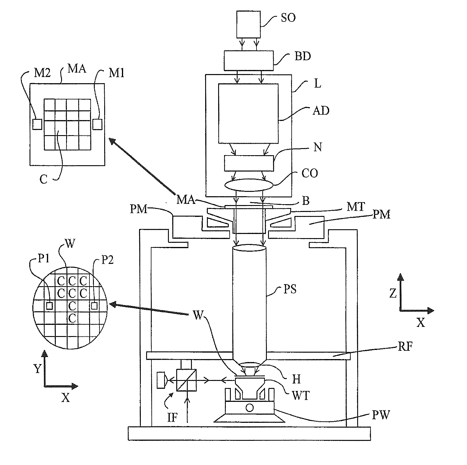
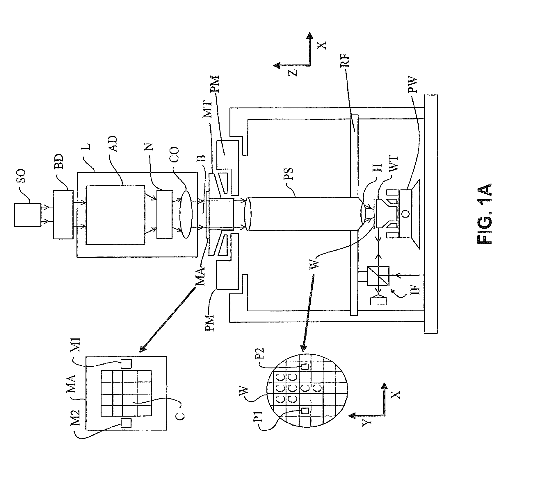
[0009]It is desirable to provide a lithographic apparatus which reduces the aforementioned problems.

Problems solved by technology

The specific discrete wavelengths are often limited to the types of sources commercially available.
If the optimal narrow band of radiation required for a particular alignment mark or lithographic process falls in between, or outside of, a set of discrete set point options, the alignment performance will be adversely affected, perhaps to the level that alignment is not possible.
This limitation reduces the flexibility to modify lithographic processes and / or alignment marks.

Method used


Image

  • Tunable Wavelength Illumination System
  • Tunable Wavelength Illumination System
  • Tunable Wavelength Illumination System

Examples


Embodiment Construction

[0024]The invention will be better understood from the following descriptions of various “embodiments” of the invention. Thus, specific “embodiments” are views of the invention, but each does not itself represent the whole invention. In many cases individual elements from one particular embodiment may be substituted for different elements in another embodiment carrying out a similar or corresponding function. The scope of the invention is not limited to the disclosed embodiment(s). The invention is defined by the claims appended hereto.

[0025]The embodiment(s) described, and references in the specification to “one embodiment”, “an embodiment”, “an example embodiment”, etc., indicate that the embodiment(s) described can include a particular feature, structure, or characteristic, but every embodiment cannot necessarily include the particular feature, structure, or characteristic. Moreover, such phrases are not necessarily referring to the same embodiment. Further, when a particular fea...


PUM


Abstract

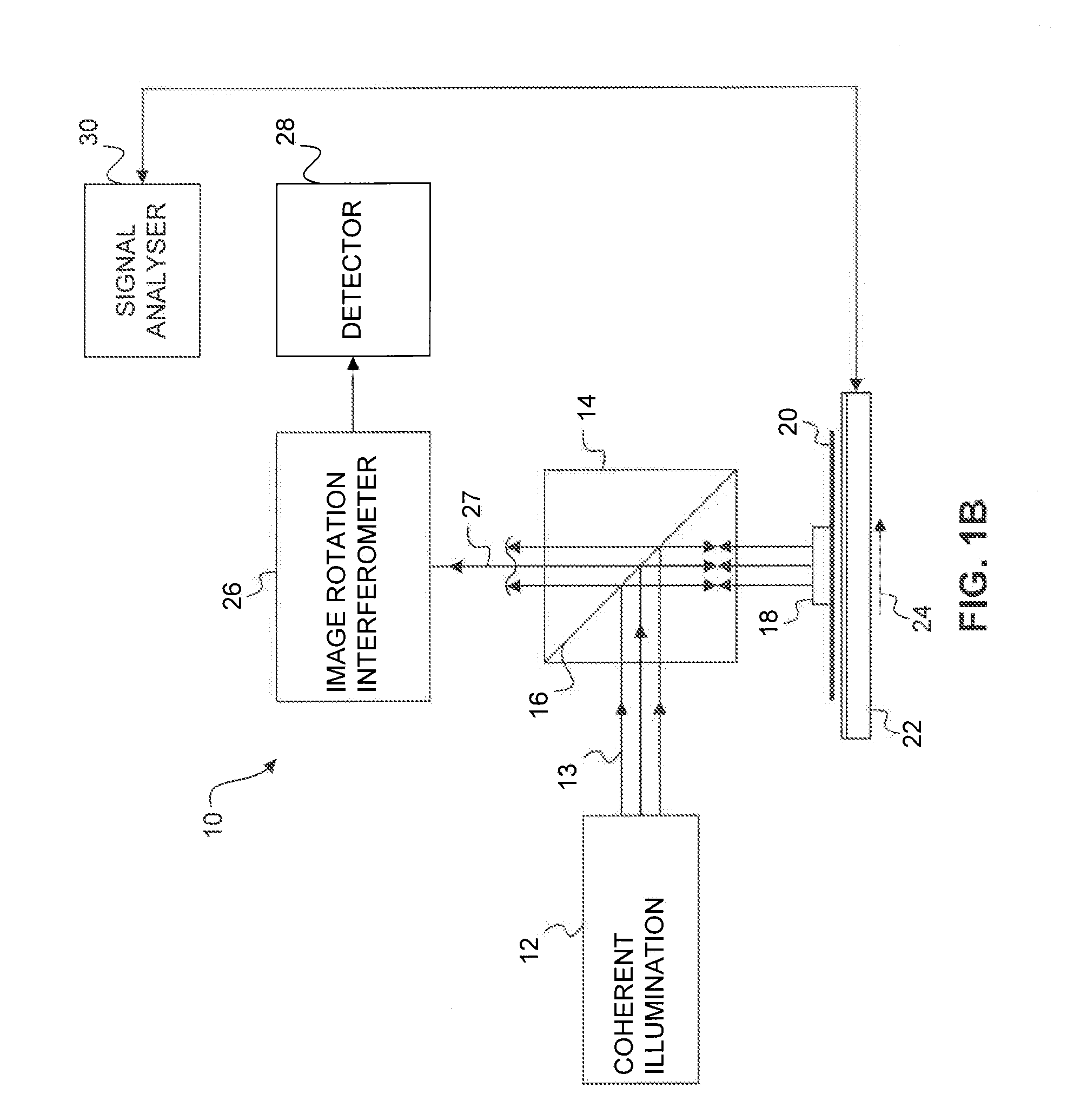
A lithographic apparatus has an alignment system including a radiation source configured to convert narrow-band radiation into continuous, flat and broad-band radiation. An acoustically tunable narrow pass-band filter filters the broad-band radiation into narrow-band linearly polarized radiation. The narrow-band radiation may be focused on alignment targets of a wafer so as to enable alignment of the wafer. In an embodiment, the filter is configured to modulate an intensity and wavelength of radiation produced by the radiation source and to have multiple simultaneous pass-bands. The radiation source generates radiation that has high spatial coherence and low temporal coherence.

Description

CROSS REFERENCE TO RELATED APPLICATIONS[0001]This patent application claims the benefit of U.S. Provisional Patent Application No. 61 / 168,095 filed on Apr. 9, 2009, entitled “Tunable Wavelength Illumination System”, which is incorporated by reference herein in its entirety.BACKGROUND[0002]1. Field of Invention[0003]The present invention generally relates generally to an illumination system of the type used in lithographic apparatus for semiconductor wafer manufacture.[0004]2. Related Art[0005]A lithographic apparatus applies a desired pattern onto a substrate, usually onto a target portion of the substrate. A lithographic apparatus can be used, for example, in the manufacture of integrated circuits (ICs). In that instance, a patterning device, which is alternatively referred to as a mask or a reticle, may be used to generate a circuit pattern to be formed on an individual layer of the IC. This pattern can be transferred onto a target portion (e.g., comprising part of, one, or severa...

Claims


Application Information

Patent Timeline
Patent Type & Authority Applications(United States)
IPC IPC(8): G06K9/00
CPCG03F9/7065G01B11/14G03F7/70141G02F1/116G03F7/70191H01L21/0231H01L21/0275H01L21/681
Inventor DEN BOEF, ARIE JEFFREYSEWELL, HARRYANDRESEN, KEITH WILLIAMEBERT, JR., EARL WILLIAMSINGH, SANJEEV KUMAR
Owner ASML HLDG NV
Learn More