
Oxygen vaporization method and system

Active Publication Date: 2011-04-14
PRAXAIR TECH INC
View PDF11 Cites 3 Cited by
  • Summary
  • Abstract
  • Description
  • Claims
  • Application Information

AI Technical Summary

Benefits of technology

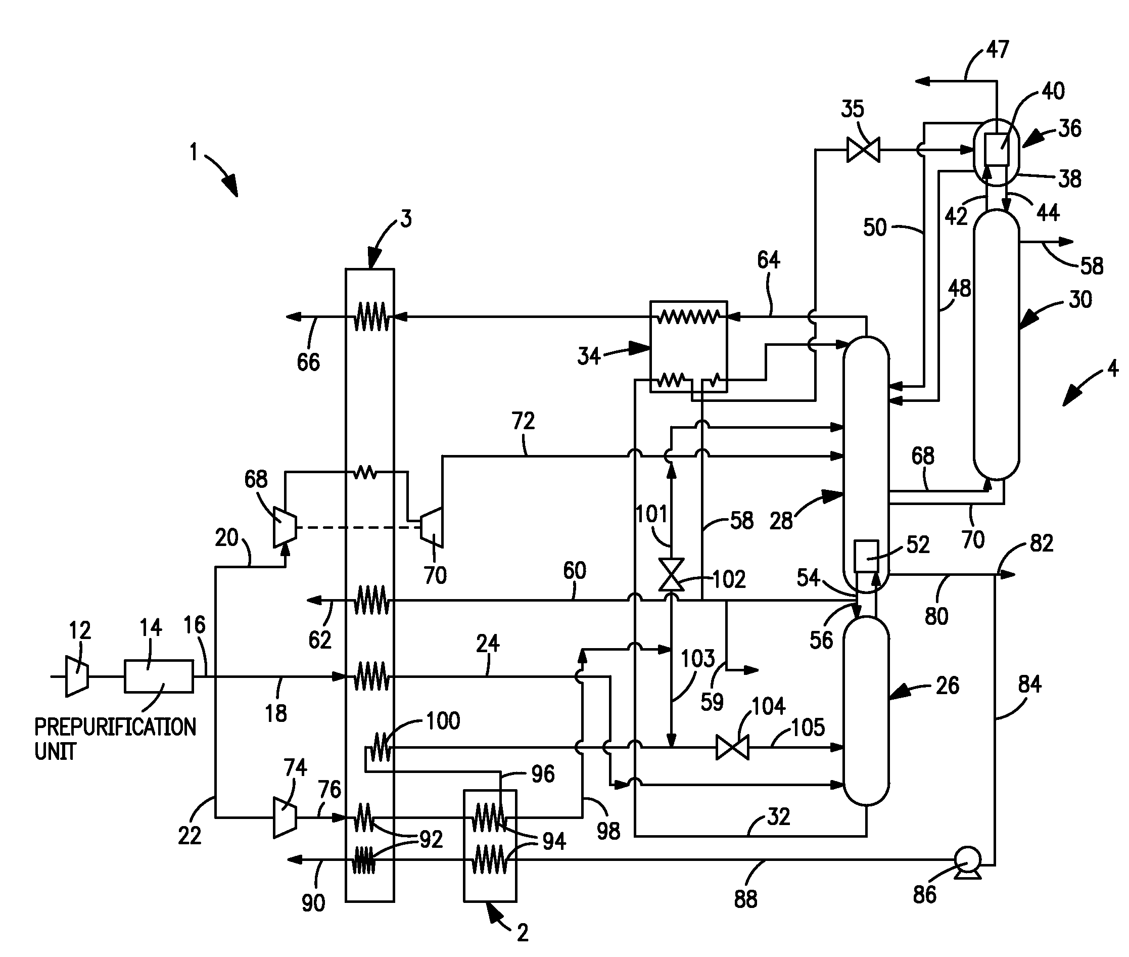
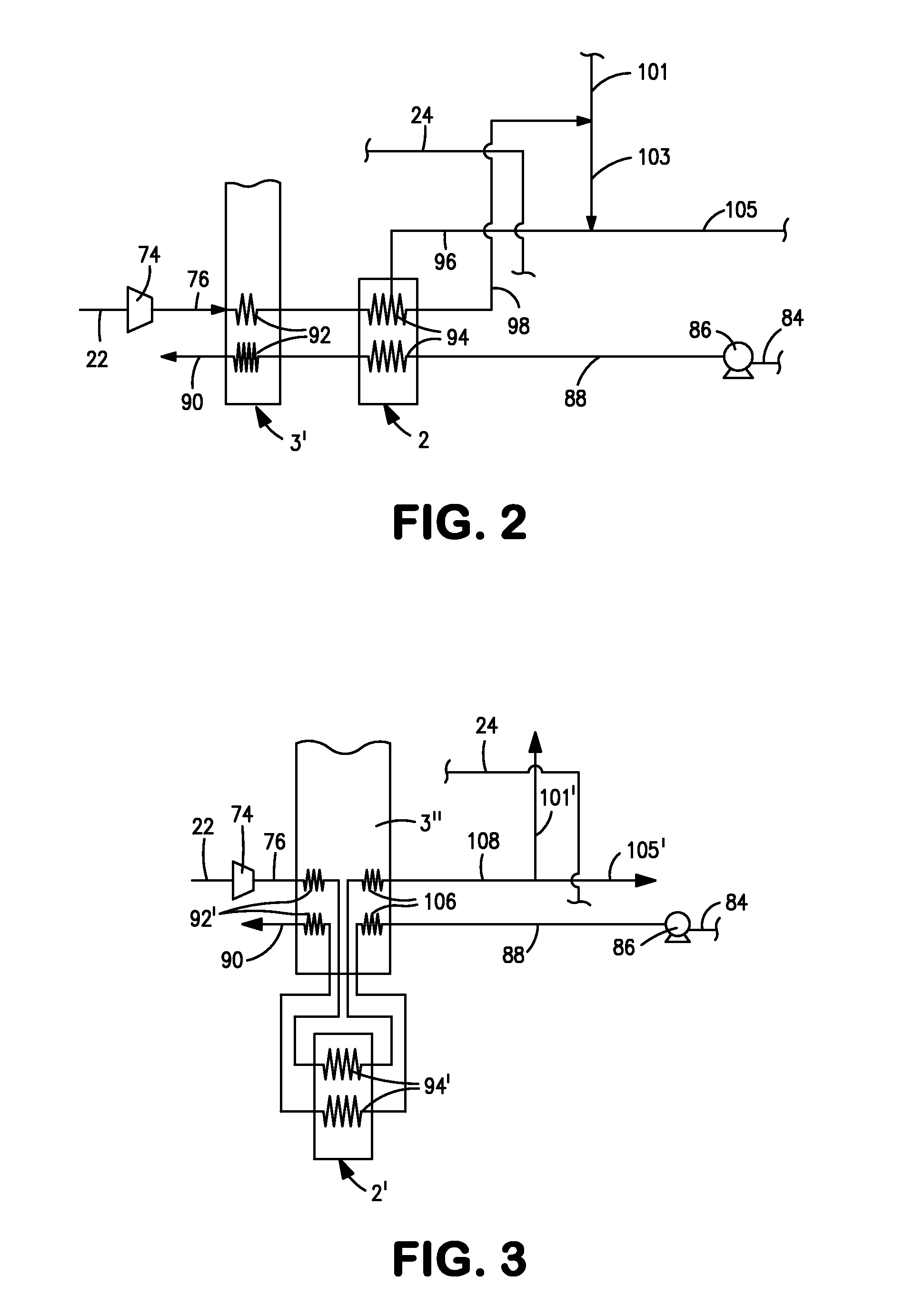
[0010]The removal of the first subcooled liquid air stream from the auxiliary heat exchanger allows the second subcooled liquid air stream to be further subcooled, resulting in such second subcooled liquid air stream be discharged from the cold end of the main heat exchanger at a lower temperature than that possible in prior art heat exchange arrangements incorporating auxiliary heat exchangers. The colder stream will have the effect of increasing the oxygen recovery and also, possibly the argon recovery if argon is to be recovered.

Problems solved by technology

The problem in conducting the vaporization of the pumped oxygen-rich liquid and the liquefaction of air entirely within the main heat exchanger is that a considerable length of the main heat exchanger is taken up in the transfer of latent heat for the vaporization of the oxygen-rich liquid and the liquefaction of the air.
This leads to higher fabrication costs of the main heat exchanger.
At the same time, since all passages within the main heat exchanger can become longer for such purposes, there are increased pressure losses within the main heat exchanger and therefore, increased power costs in the compression of the air.
While this arrangement incorporating the auxiliary heat exchanger results in a shorter heat exchanger, the degree to which the liquid air is subcooled is very limited given the amount of air that must be consumed in vaporizing the liquid oxygen and the amount of sensible heat that can be transferred from the oxygen-rich liquid to the liquid air within the auxiliary heat exchanger.
Unfortunately, the degree to which the liquid air is subcooled will have an effect on oxygen and potentially argon recovery, if present, given that the colder the liquid air upon entry to the low pressure column, the greater degree to which oxygen and argon is driven down the column.

Method used


Image

  • Oxygen vaporization method and system
  • Oxygen vaporization method and system
  • Oxygen vaporization method and system

Examples


Embodiment Construction

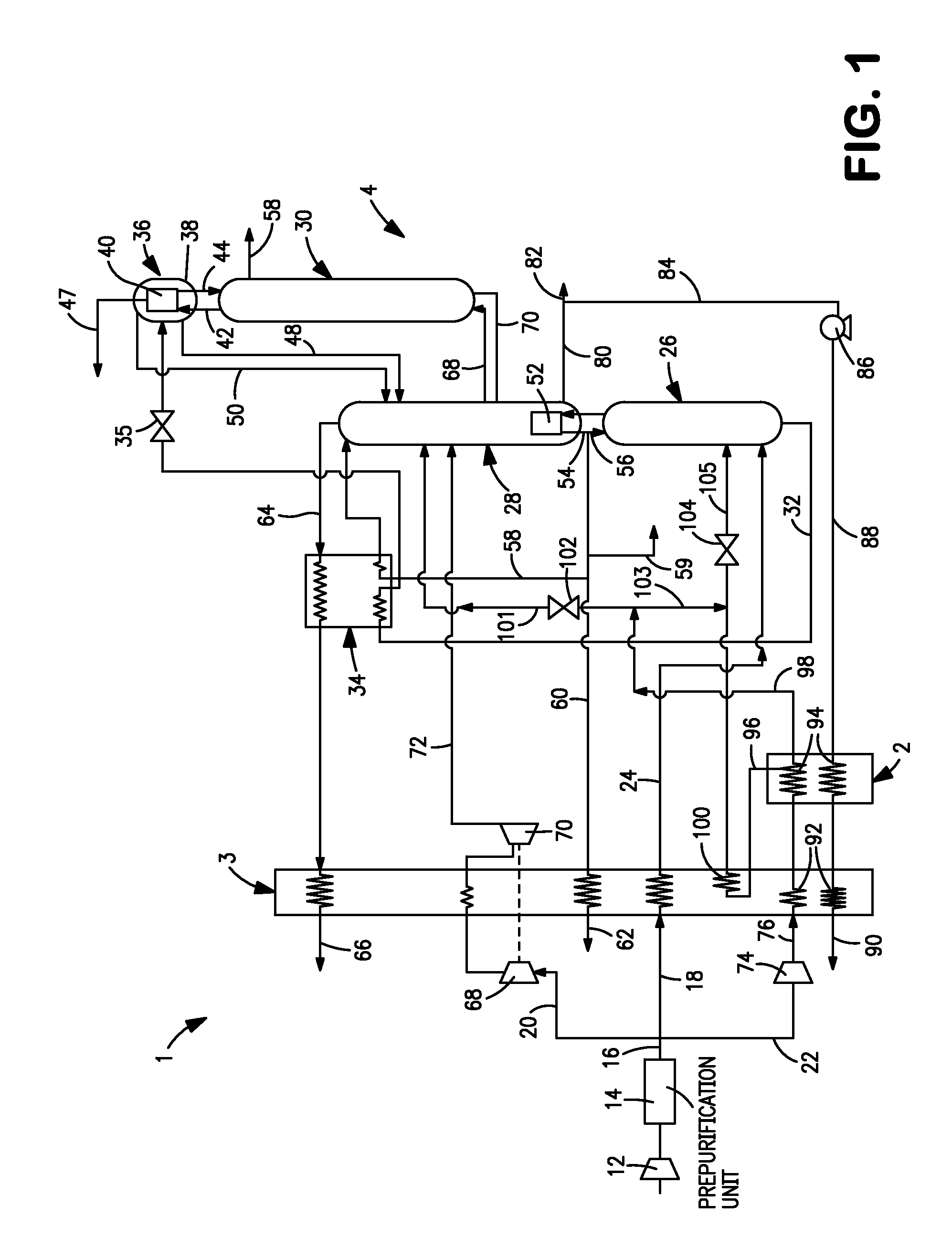
[0025]With reference to FIG. 1, an air separation plant 1 is illustrated that incorporates a heat exchange system in accordance with the present invention that, as will be discussed in more detail hereinafter, is an integration of an auxiliary heat exchanger 2 and a main heat exchanger 3 that together function to vaporize pressurized oxygen and liquefy compressed air that serves as part of the feed to a distillation column system 4. It is understood, however, that air separation plant 1 and the discussion thereof is for purposes of illustration as the present invention would have applicability to air separation plants employing a different arrangement of columns. In this regard, although the present invention is illustrated as having an argon column 30, to be discussed, the present invention is applicable to a column arrangement where argon is not recovered and hence, there exists no argon column.

[0026]In air separation plant 1, a feed air stream 10 is compressed by a main air compr...


PUM


Abstract

A method and system for producing an oxygen product stream in which sensible heat from a compressed air stream is indirectly exchanged with a vaporized pumped liquid oxygen stream in a main heat exchanger and latent heat is exchanged in an auxiliary heat exchanger connected to the main heat exchanger. The latent heat exchange produces subcooled liquid air that is fed into a low pressure column of the air separation plant and vaporization of the pumped liquid. Part of the subcooled liquid air can be withdrawn from the auxiliary heat exchanger at a higher temperature than the remainder of the subcooled liquid air. All or part of the subcooled liquid air can be further cooled within the main heat exchanger. As a result, low temperature, subcooled liquid air is produced that allows for an increased oxygen recovery and also, argon recovery if an argon column is present.

Description

FIELD OF THE INVENTION [0001]The present invention relates to an oxygen vaporization method and system for use in a cryogenic air separation plant in which an oxygen-rich liquid stream, withdrawn from a low pressure column, is pumped and then vaporized through indirect heat exchange with a compressed air stream resulting in liquefaction of the air stream. More particularly, the present invention relates to such a method and system in which latent heat is exchanged between the air stream and the pumped oxygen-rich liquid in an auxiliary heat exchanger.BACKGROUND OF THE INVENTION[0002]Oxygen is produced in air separation plants that employ a cryogenic rectification process to separate the air into its component parts. In such a plant, the air is compressed, purified and cooled within a main heat exchanger to a temperature suitable for its rectification within distillation column. Typically, such plants utilize an air separation unit having higher and low pressure distillation columns ...

Claims


Application Information

Patent Timeline
IPC IPC(8): F25J3/00F17C9/02
CPCF17C2201/0109F17C5/00F17C2205/0323F17C2205/0341F17C2221/011F17C2221/014F17C2221/016F17C2223/0123F17C2223/0161F17C2223/0169F17C2223/033F17C2223/035F17C2227/0135F17C2227/0157F17C2227/0185F17C2227/0306F17C2227/0339F17C2227/039F17C2265/01F17C2270/05F25J3/0409F25J3/04206F25J3/04218F25J3/04303F25J3/04412F25J3/04678F25J2250/40F25J2250/50F17C2201/056F25J3/00
Inventor ROOKS, RAYMOND EDWIN
Owner PRAXAIR TECH INC
Learn More