Pulse pump
a pump and pump body technology, applied in the direction of flexible member pumps, machines/engines, positive displacement liquid engines, etc., can solve the problems of preventing the flow of fluid from reaching the drainage network beneath the floor, the drain tube extending from this equipment to the drainage network can become blocked, and the buildup of fluid is difficult to eliminate within the relatively small drain tube passages
- Summary
- Abstract
- Description
- Claims
- Application Information
AI Technical Summary
Benefits of technology
Problems solved by technology
Method used
Image
Examples
first embodiment
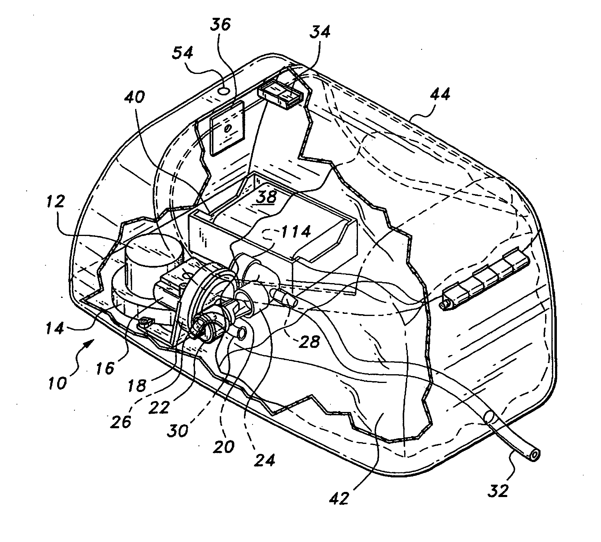
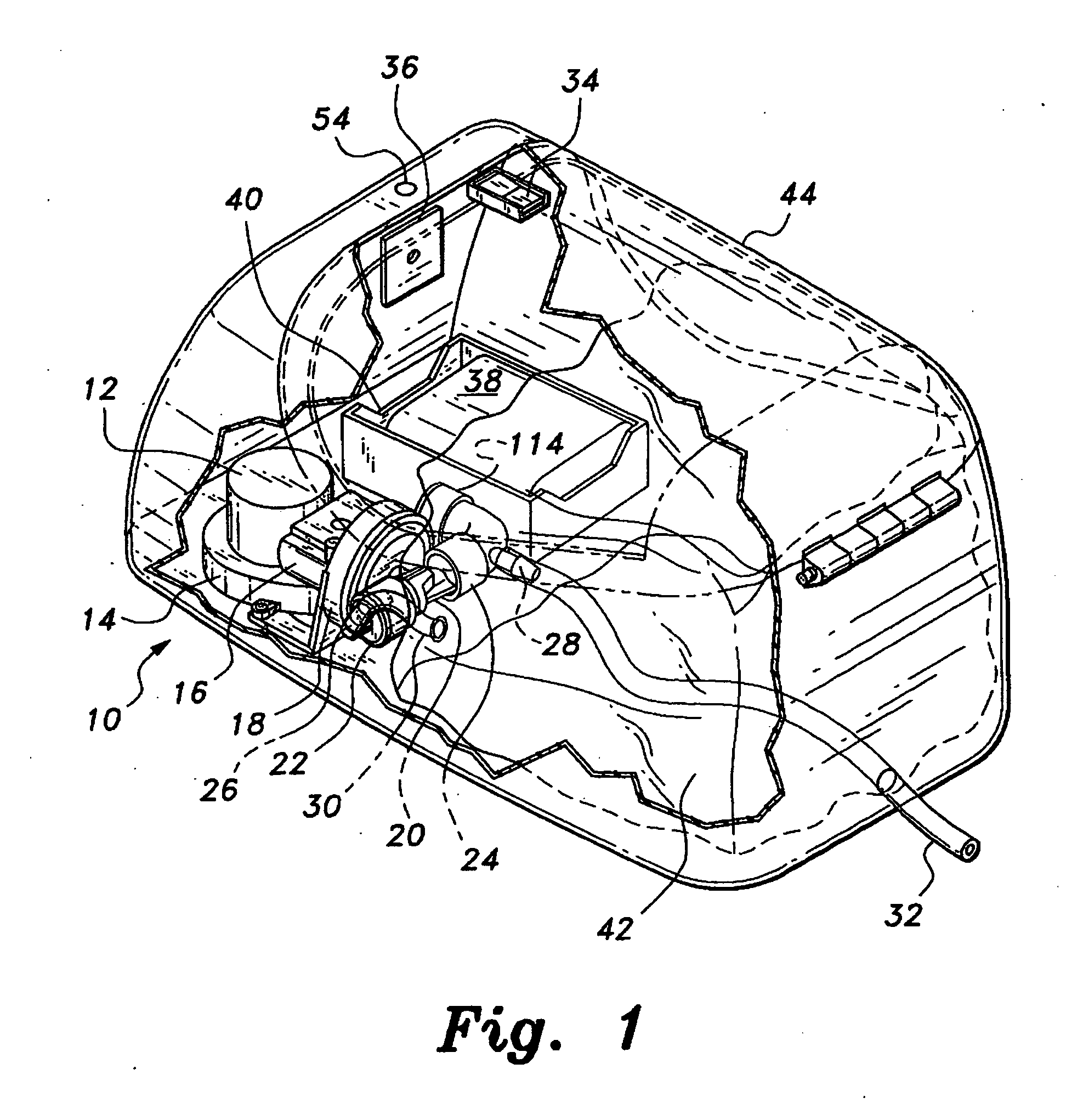
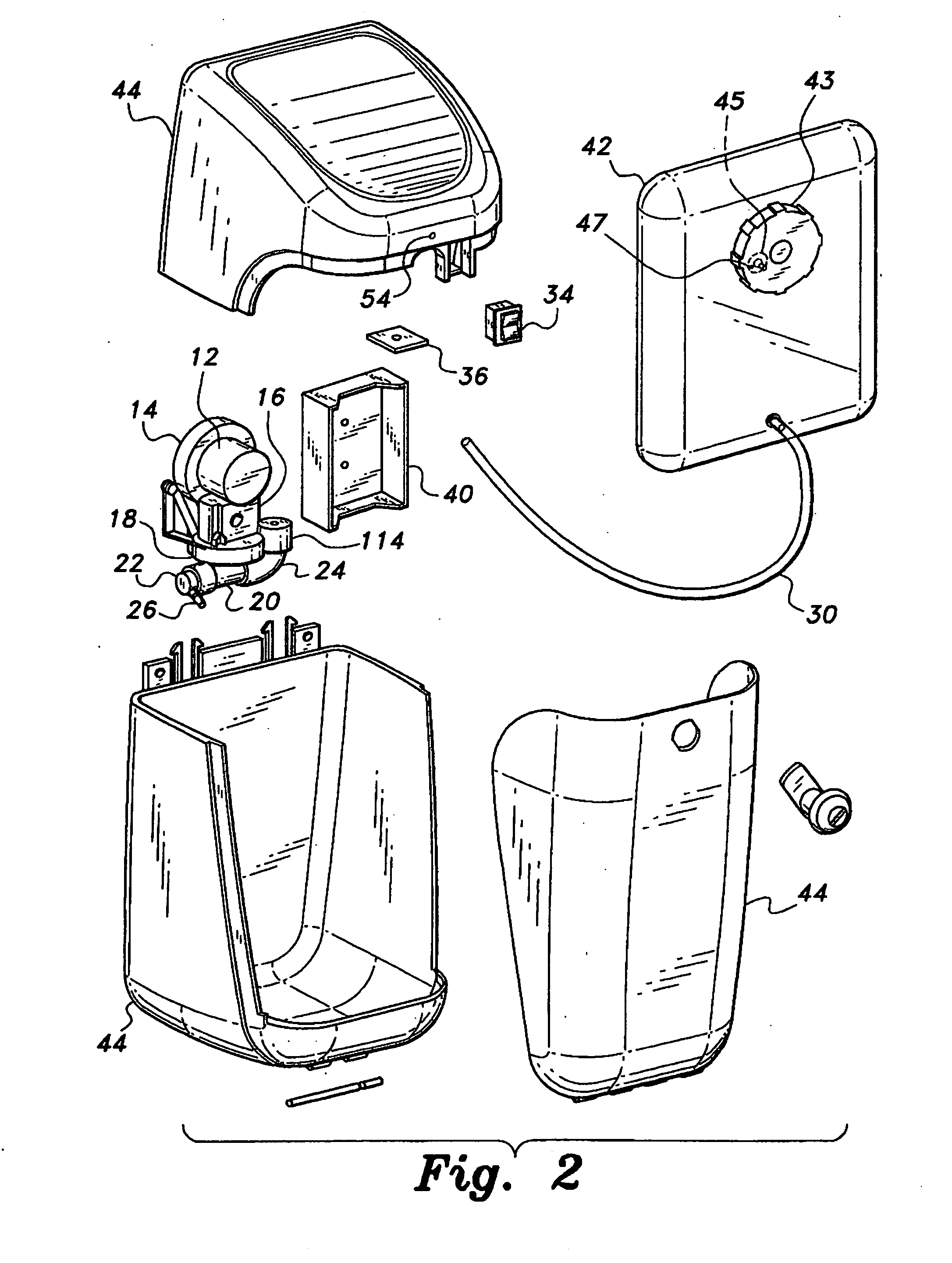
[0036]FIG. 4 of the drawings provides a view of the pump assembly 10 of the first embodiment with the cover of the actuator mechanism removed, to show more clearly the details of this mechanism. A non-circular output shaft 46 extends from the gear reduction drive 14, and extends into or through an axially offset mating passage in an eccentric rotor 48. As the output shaft 46 rotates, the rotor 48 oscillates eccentrically due to the non-concentric installation of the output shaft 46 therein. The rotor 48 resides within an oval-shaped passage 50 within the reciprocating diaphragm actuator 52, which in turn drives the diaphragm assembly 18 as explained further below. The rotor 48 is free to oscillate laterally within the oval passage 50 of the actuator 52, but the narrower vertical dimension (i.e., normal to the plane of the diaphragm) of the oval passage 50 results in the rotor 48 drawing the reciprocating actuator 52 upwardly and downwardly relative to the plane of the diaphragm (ill...
embodiment 210
[0060]The first inlet valve assembly 22a has an inlet line connector or fitting 26a extending therefrom, which would connect to the supply line 30 from the reservoir 42 if the pump assembly 210 were installed in lieu of the pump assembly 10 of FIG. 1. The opposite outlet line connector or fitting 28a communicates with the second inlet connector or fitting 26b of the second inlet valve assembly 22b via an intermediate tube 30a. In a like manner, the outlet fitting 28b of the second outlet valve assembly 24b communicates with the inlet fitting 26c of the third inlet valve assembly 22c via another intermediate tube 30b, with the third outlet fitting 28c of the third outlet valve assembly 24c communicating with the inlet fitting 26d of the fourth inlet valve assembly 22d. Finally, the outlet fitting 28d of the fourth outlet valve assembly 24d connects to an outlet line, e.g., the line 32 of the pump assembly shown in FIG. 1, if the multiple valve pump 210 were used in lieu of the single...
embodiment 10
[0061]Otherwise, it will be seen that the multiple diaphragm and valve pulse pump system includes various features found in the various embodiments of the single diaphragm assembly 10 of FIGS. 1 through 9B. For example, the fourth or final outlet valve 24d includes an anti-siphon valve assembly 114 extending therefrom, which function is identical to that described further above for the pulse pump embodiment 10. It will also be seen that while a series of four diaphragms 80a through 80d and corresponding valve bodies 20a through 20d, inlet valve assemblies 22a through 22d, and outlet valve assemblies 24a through 24d with their inlet and outlet valves 110a through 112d are shown in FIGS. 10 through 13, other arrangements or configurations may be constructed in keeping with the concept described above. For example, two of the four diaphragm actuator plates may be eliminated during assembly, with only two diaphragms and two inlet and outlet valve assemblies remaining operable and interc...
PUM
 Abstract
Description
Claims
Application Information
 - R&D Engineer
- R&D Manager
- IP Professional
- Industry Leading Data Capabilities
- Powerful AI technology
- Patent DNA Extraction
Browse by: Latest US Patents, China's latest patents, Technical Efficacy Thesaurus, Application Domain, Technology Topic, Popular Technical Reports.
© 2024 PatSnap. All rights reserved.Legal|Privacy policy|Modern Slavery Act Transparency Statement|Sitemap|About US| Contact US: help@patsnap.com


