Apparatus and method for driving rotary machine
a technology of electric machines and apparatuses, applied in the direction of electronic commutation motor control, motor/generator/converter stoppers, dynamo-electric converter control, etc., can solve the problems of reducing the starting time of the conventional apparatus, bringing into a state of loss of synchronism, and stopping the rotation of the motor
- Summary
- Abstract
- Description
- Claims
- Application Information
AI Technical Summary
Benefits of technology
Problems solved by technology
Method used
Image
Examples
fifth embodiment
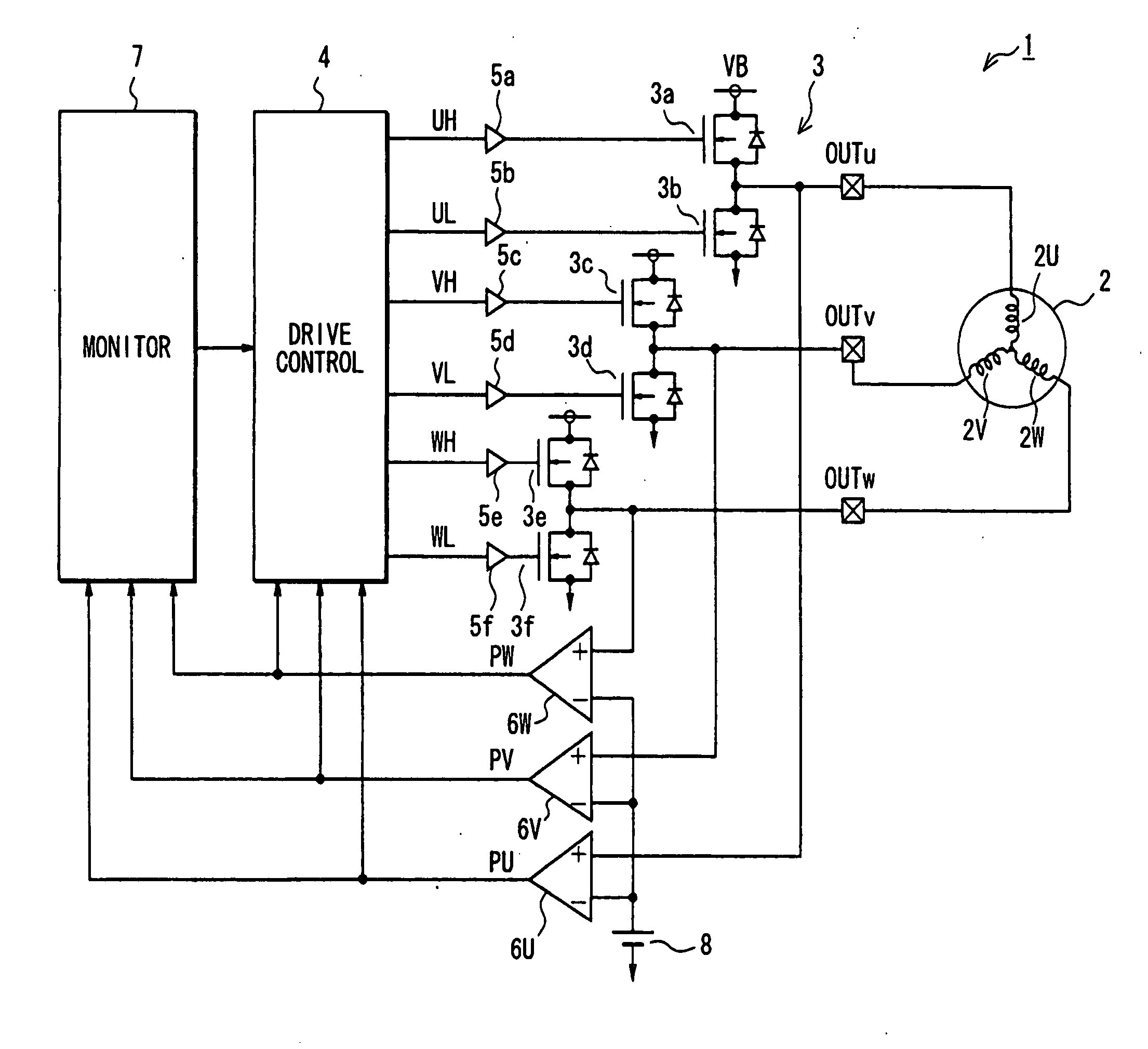
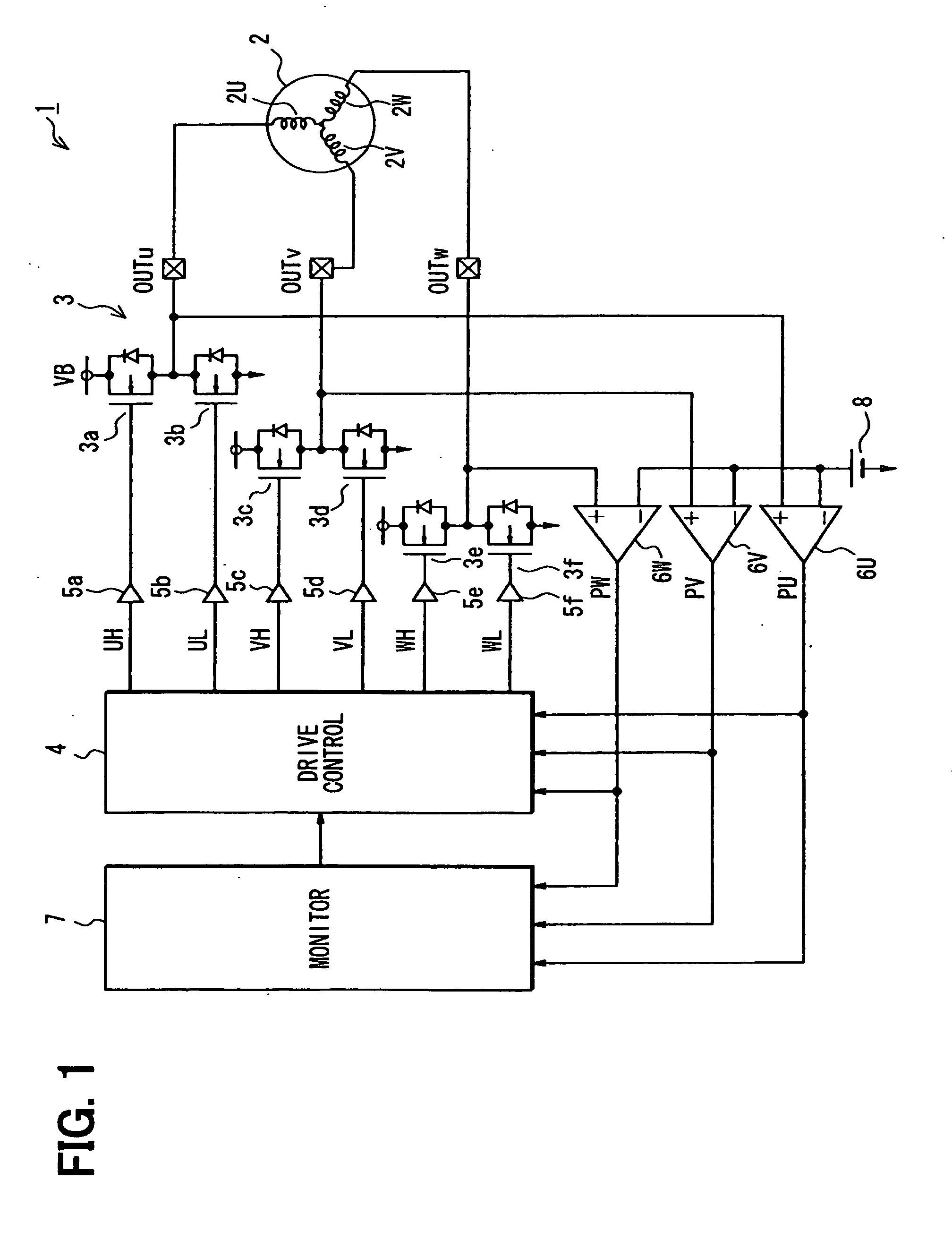
[0132]In a fifth embodiment illustrated in FIG. 11, a rotary machine driving apparatus 1 is configured to drive a motor for driving, for example, a mini disk (MD) or a hard disk drive (HDD). This rotary machine driving apparatus 1 is similar to that of the first embodiment (FIG. 1), but has no loss-of-synchronism monitoring circuit. However, a drive control circuit 4 includes an internal counter (not illustrated) to measure an interval between the edges of the position signals PU′, PV′, PW′ to measure a zero-cross period T60 corresponding to electrical angle of 60° as illustrated in FIG. 12, (g). The zero-cross time point of the induced voltage has a phase delay of an electrical angle of 30° from an appropriate energization time point. Therefore, the drive control circuit 4 generates a commutation pattern by compensating for the phase delay. The time interval corresponding to the electric angle of 30° may be determined as T60 / 2. The waveforms of the output voltage of the inverter un...
sixth embodiment
[0154]In a sixth embodiment illustrated in FIG. 18, a rotary machine driving apparatus is provided for a brushless DC motor 2, which may be provided in a vehicle as a rotary machine.
[0155]The motor 2 is a three-phase motor and an actuator of a fuel pump for an internal combustion engine mounted in a motorcycle. The three phases (U-phase, V-phase, W-phase) of the brushless motor 2 are connected with an inverter 12. The inverter 12 is a three-phase inverter and applies the voltage of a battery 214 to the three phases of the brushless motor 2. To provide conduction between each of the three phases and the positive pole and negative pole of the battery 214, the inverter 12 is so constructed that it includes a parallel connection unit having: switching elements SW1, SW2 (U-phase arm), switching elements SW3, SW4 (V-phase arm), and switching elements SW5, SW6 (W-phase arm). The junction point between the switching element SW1 and the switching element SW2 connected in series is connected ...
seventh embodiment
[0198]In a seventh embodiment, the acceleration of the brushless motor 2 is detected based on a detected value of zero-crossing time, and the setting of a permitted period is corrected based on this acceleration. FIG. 26A illustrates processing for correcting the setting of a permitted period. This processing is repeatedly carried out by the drive control circuit 220, for example, in a predetermined cycle. This series of processing is carried out as follows.
[0199]At S90, the acceleration A of the brushless motor 2 is calculated based on the previous maximum value of the counter and the present maximum value of the counter. The maximum value may be determined based on the value Cm (FIG. 19) of the measuring counter. The maximum value of the counter is for counting the time interval between zero-crossing times, and has correlation with the instantaneous rotational speed between zero-crossing times. For this reason, these two values, the previous maximum value of the counter and the pr...
PUM
 Abstract
Description
Claims
Application Information
 - R&D
- Intellectual Property
- Life Sciences
- Materials
- Tech Scout
- Unparalleled Data Quality
- Higher Quality Content
- 60% Fewer Hallucinations
Browse by: Latest US Patents, China's latest patents, Technical Efficacy Thesaurus, Application Domain, Technology Topic, Popular Technical Reports.
© 2025 PatSnap. All rights reserved.Legal|Privacy policy|Modern Slavery Act Transparency Statement|Sitemap|About US| Contact US: help@patsnap.com


