
Integrated Photonics Device

a photonics and integrated technology, applied in the field of integrated photonics, can solve the problems of inconvenient approach, inconvenient coupling between high index contrast waveguides and optical fibers, and unnecessary facets

Active Publication Date: 2011-03-31
INTERUNIVERSITAIR MICRO ELECTRONICS CENT (IMEC VZW) +1
View PDF28 Cites 33 Cited by
  • Summary
  • Abstract
  • Description
  • Claims
  • Application Information

AI Technical Summary

Benefits of technology

[0008]It is an object of the present invention to provide good methods and systems for optically coupling between an optical element and an integrated photonic device, as well as methods for making such systems.
[0009]It is an advantage of embodiments according to the present invention that systems and methods are provided whereby good optical coupling can be obtained using integrated components, thus avoiding complex or fault-sensitive positioning or mounting.
[0010]It is an advantage of embodiments of the present invention that user-friendly systems and methods are obtained.

Problems solved by technology

Efficient coupling between a high index contrast waveguide and an optical fiber is an important issue, but can be difficult due to the large mismatch in mode size and mode shape between the fundamental mode of the waveguide and the mode of the optical fiber.
Furthermore, the out-of-plane approach can make polished facets unnecessary and can enable wafer scale testing of integrated optical circuits.
However, this approach has several inconveniences.
A first inconvenience is the limited efficiency of coupling between optical fiber and silicon waveguide modes.
A second inconvenience is the need for an adiabatic taper, which typically can be on the order of 500 μm long.
One major inconvenience in the use of out-of-plane coupling is that substantially vertical coupling (i.e. coupling in a direction that is substantially perpendicular to the average plane of the integrated optical circuit) tends to suffer from large second-order Bragg reflection back into the waveguide (e.g., when coupling light between a waveguide and a fiber).
When typical gratings are designed for perfectly vertical or substantially vertical coupling, the second Bragg diffraction order can cause large reflections, resulting in a low coupling efficiency.
However, this approach would not be completely satisfactory because reflections are only canceled in a narrow wavelength range.
Light generation in silicon is difficult and therefore there is a need for integrating optical components based on other materials, such as for example optical components comprising III-V semiconductors, on silicon integrated photonic circuits.
However, the yield and reliability of these techniques are currently too low for commercial application.
Moreover, the etching of angled facets on horizontal cavity lasers is a complicated, expensive and time-consuming process.
However, this type of grating coupler has not yet been experimentally demonstrated and it does not function in a broad wavelength range.

Method used


Image

  • Integrated Photonics Device
  • Integrated Photonics Device
  • Integrated Photonics Device

Examples


Embodiment Construction

[0040]In the following detailed description, numerous specific details are set forth in order to provide a thorough understanding of the invention and how it may be practiced in particular embodiments. However it will be understood that the present invention may be practiced without these specific details. In other instances, well-known methods, procedures and techniques have not been described in detail, so as not to obscure the present invention. While the present invention will be described with respect to particular embodiments and with reference to certain drawings, the reference is not limited hereto. The drawings included and described herein are schematic and are not limiting the scope of the invention. It is also noted that in the drawings, the size of some elements may be exaggerated and, therefore, not drawn to scale for illustrative purposes.

[0041]Furthermore, the terms first, second and the like in the description and in the claims, are used for distinguishing between s...


PUM


Abstract

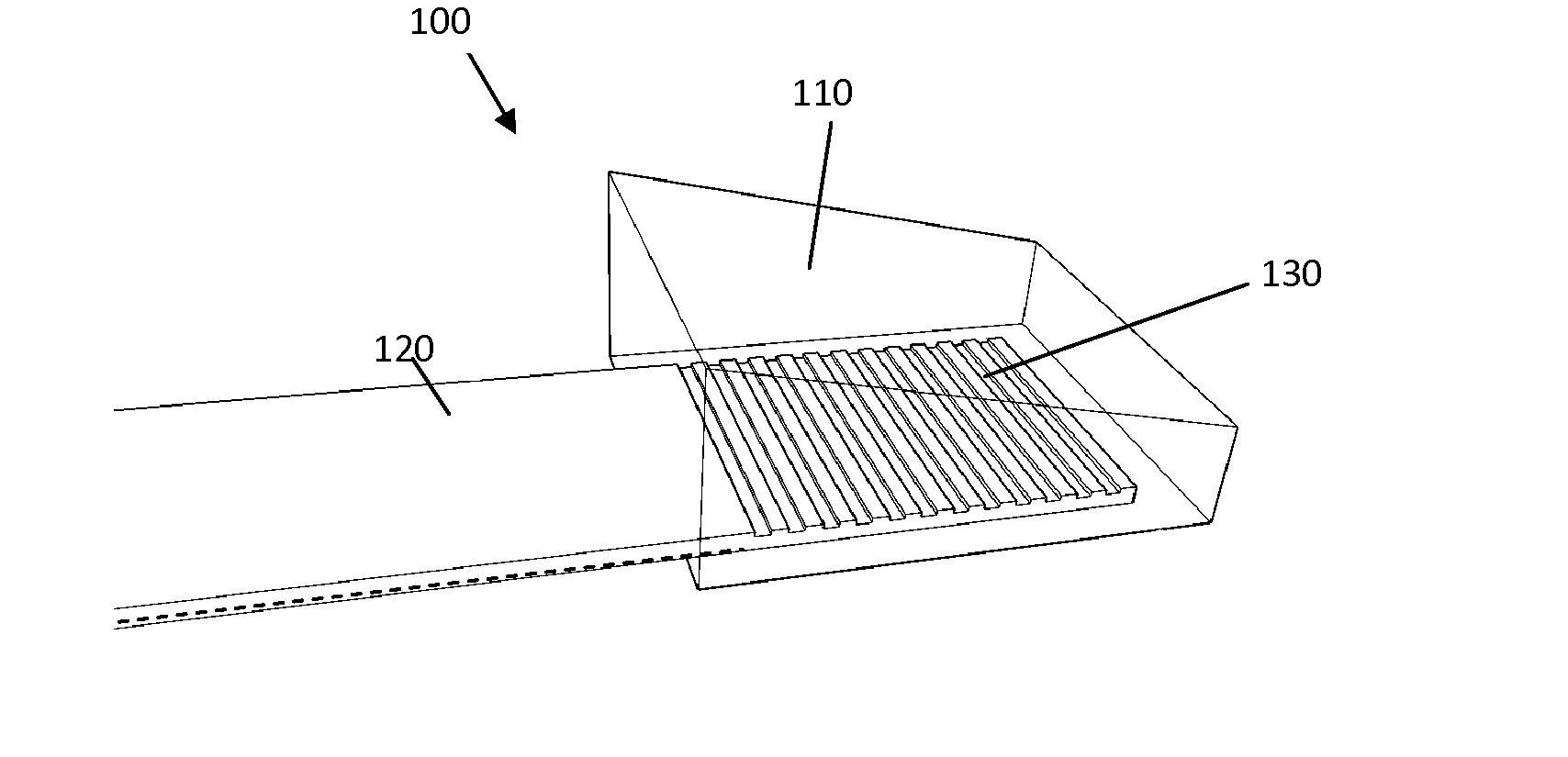
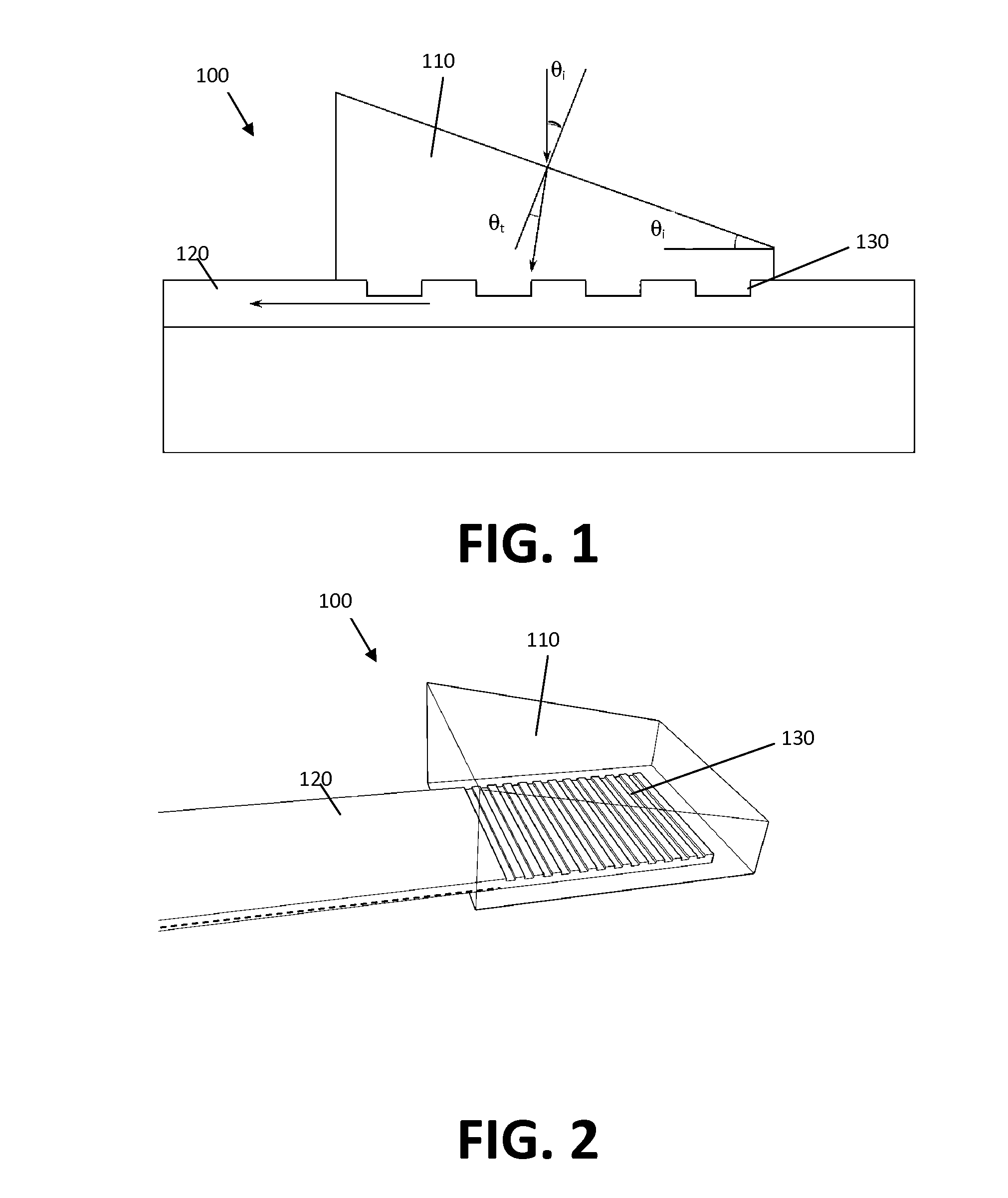
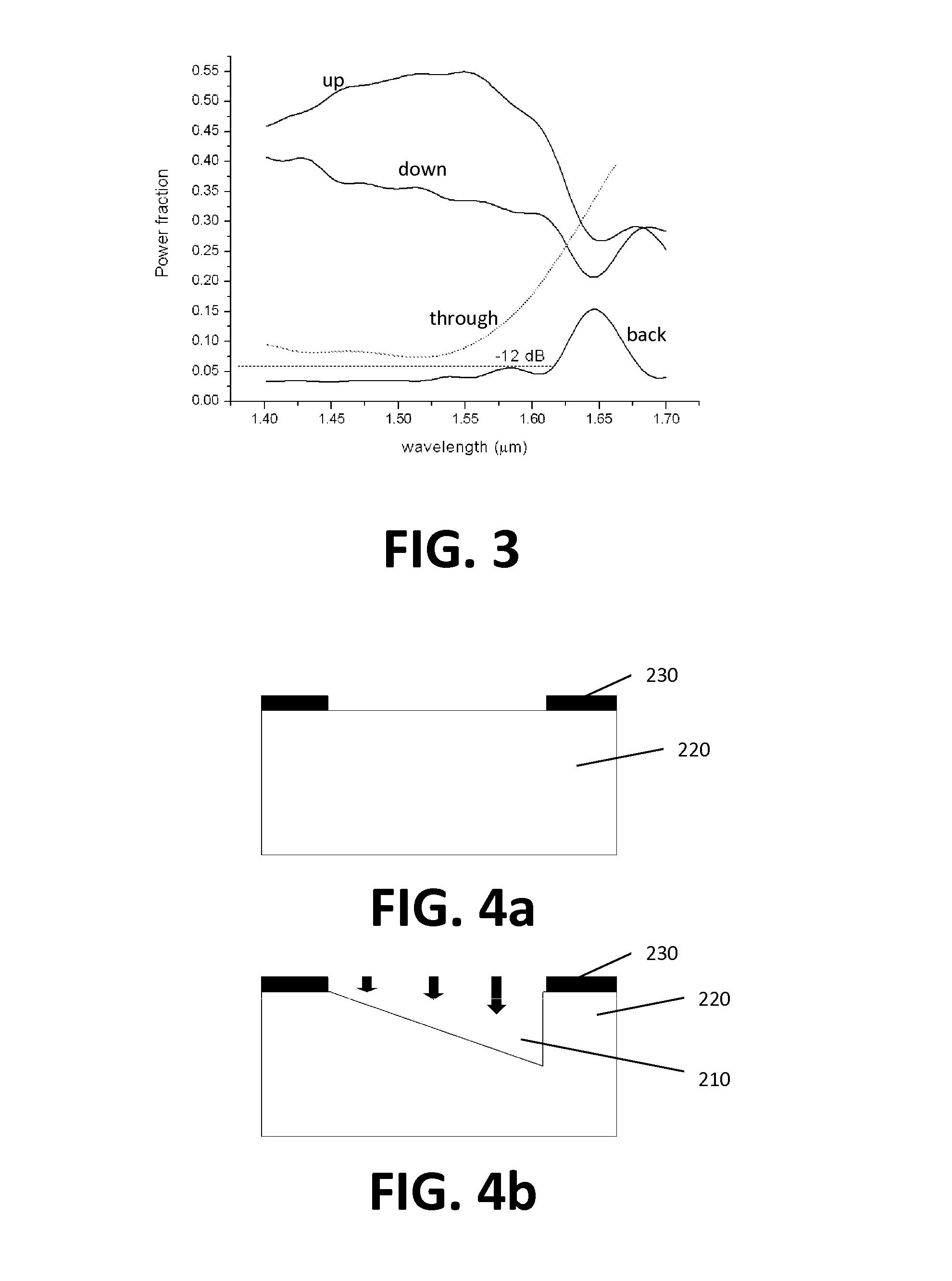
The present invention relates to an integrated photonic device (100) operatively coupleable with an optical element (300) in a first coupling direction. The integrated photonic device (100) comprises an integrated photonic waveguide (120) and a grating coupler (130) that is adapted for diffracting light from the waveguide (120) into a second coupling direction different from the first coupling direction. The integrated photonics device also comprises a refractive element (110) disposed adjacent the grating coupler (130) and adapted to refract the light emerging from the grating coupler (130) in the second coupling direction into the first coupling direction.

Description

FIELD OF THE INVENTION[0001]The present invention relates to integrated photonics. More in particular, it relates to coupling of light between an optical element and a waveguide on a photonic integrated circuit.BACKGROUND OF THE INVENTION[0002]The silicon-on-insulator (SOI) platform is a promising candidate for future ultra-compact photonic integrated circuits because of its compatibility with complementary metal-oxide semiconductor (CMOS) technology. The high index contrast between the silicon core and the oxide cladding allows for the fabrication of short waveguide bends and therefore circuits with a high degree of integration. Efficient coupling between a high index contrast waveguide and an optical fiber is an important issue, but can be difficult due to the large mismatch in mode size and mode shape between the fundamental mode of the waveguide and the mode of the optical fiber.[0003]Out-of-plane grating couplers may be used as a solution to this problem. Due to the large index...

Claims


Application Information

Patent Timeline
IPC IPC(8): G02B6/124B05D5/06
CPCG02B6/124G02B6/34G02B6/43
Inventor SCHRAUWEN, JONATHANSCHEERLINCK, STIJNROELKENS, GUNTHERVAN THOURHOUT, DRIES
Owner INTERUNIVERSITAIR MICRO ELECTRONICS CENT (IMEC VZW)
Learn More