Radiography apparatus
a technology of radiography and apparatus, applied in the field of radiography apparatus, can solve the problems of reducing the quality of reconstructed slice image, affecting the operation of the diaphragm, and the movement of the x-ray detector, so as to increase the size of the reconstructable region
- Summary
- Abstract
- Description
- Claims
- Application Information
AI Technical Summary
Benefits of technology
Problems solved by technology
Method used
Image
Examples
first embodiment
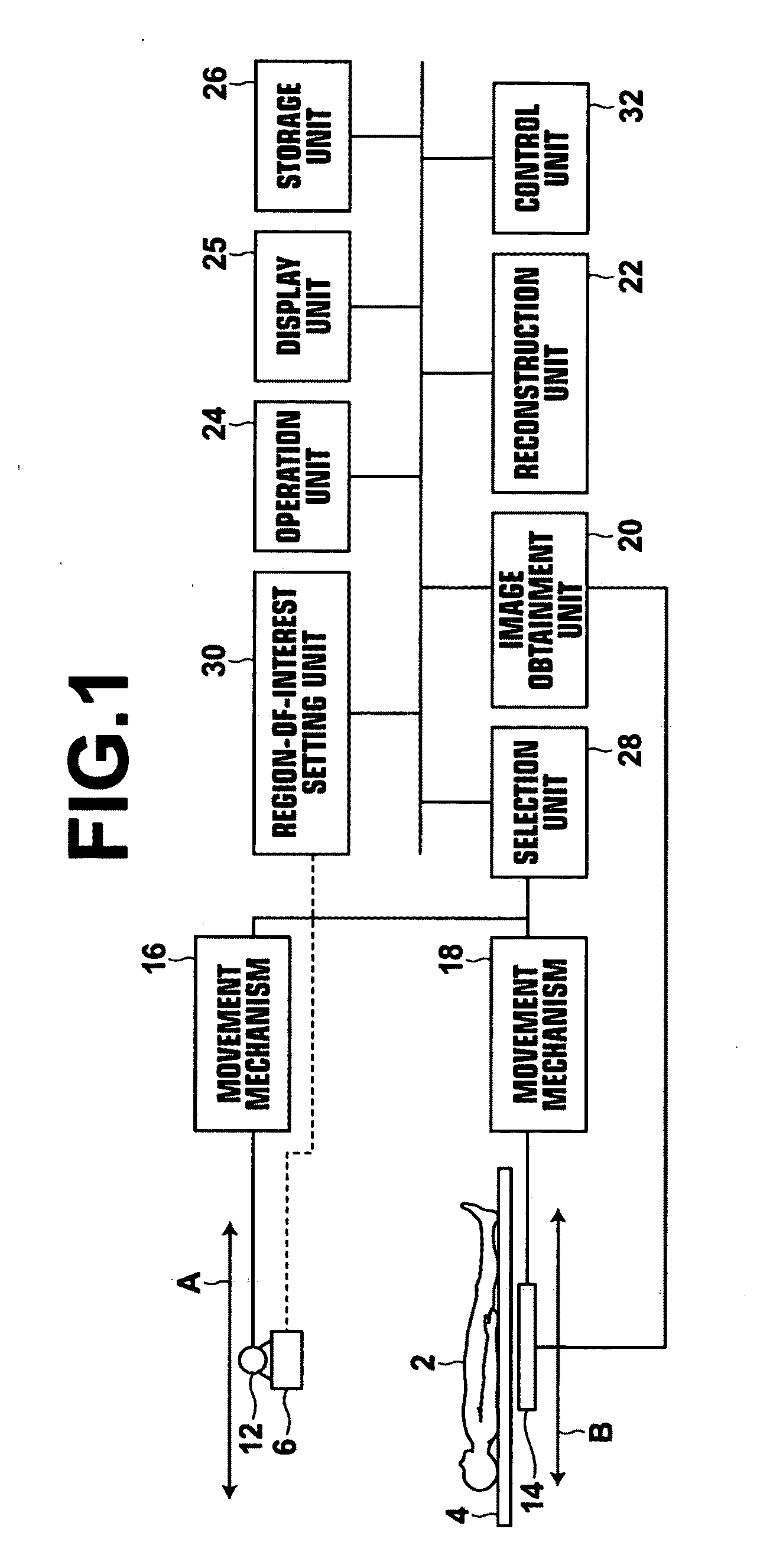
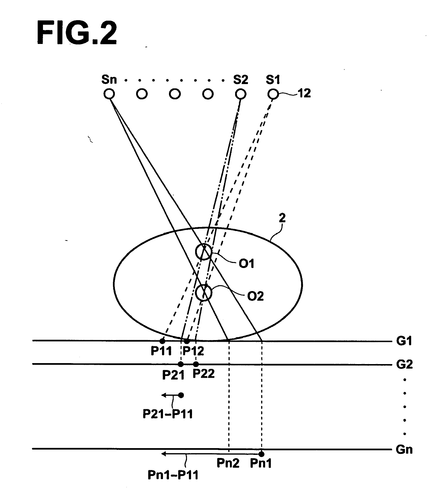
[0036]Hereinafter, embodiments of the present invention will be described with reference to drawings. FIG. 1 is a schematic diagram illustrating an X-ray radiography apparatus to which a radiography apparatus according to the present invention has been applied. As illustrated in FIG. 1, an X-ray radiography apparatus 10 according to the present embodiment includes an X-ray tube 12 and a flat-panel X-ray detector (hereinafter, simply referred to as a detector) 14. The X-ray tube 12 is moved straight or along an arc or curve by a movement mechanism 16. The X-ray tube 12 outputs, at a plurality of positions on the movement path thereof, X-rays to a subject 2 on the top board 4 of a radiographic table. In the present embodiment, it is assumed that the X-ray tube 12 moves along a straight line in the direction of arrow A. The dose of radiation of X-rays output to the subject 2 is controlled by a control unit, which will be described later, so that the dose of radiation becomes a predeter...
second embodiment
[0057]In the second embodiment, the selection unit 28 compares the region of interest that has been set by the region-of-interest setting unit 30 with the reconstructable region in the first mode. If the region of interest that has been set by the region-of-interest setting unit30 is included in the reconstructable region in the first mode, the selection unit 28 selects the first mode. However, if the region of interest that has been set by the region-of-interest setting unit 30 is not included in the reconstructable region in the first mode, in other words, if the set region of interest is larger than the reconstructable region in the first mode, the selection unit 28 selects the second mode.
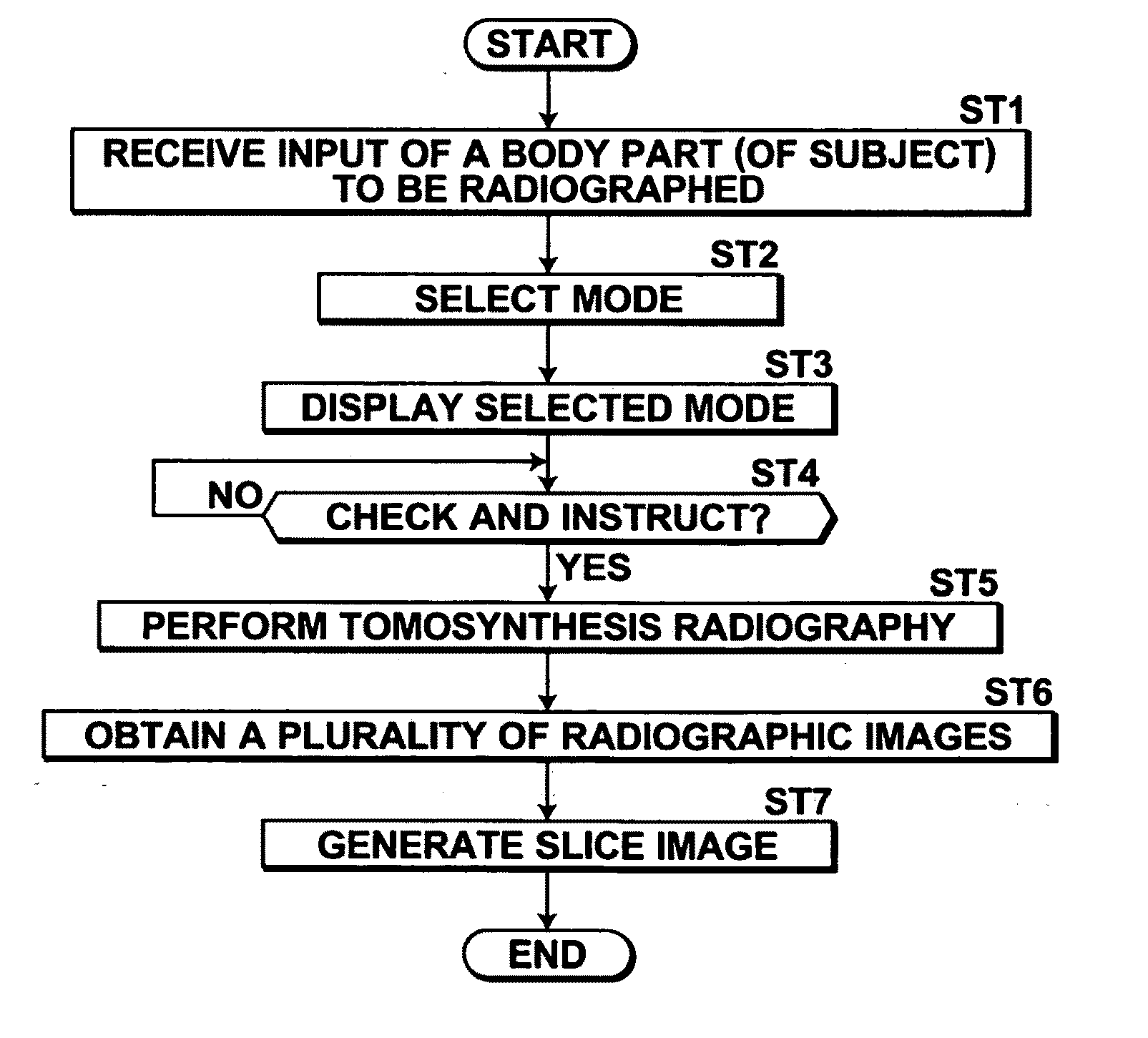
[0058]Next, processing performed in the second embodiment will be described. FIG. 8 is a flow chart illustrating the processing performed in the second embodiment. First, the control unit 32 receives setting of the range with respect to the depth direction and the range with respect to the in-p...
third embodiment
[0061]In the third mode, the detector 14 is moved to a plurality of positions, and the detector 14 is fixed at each of the plurality of positions. Then, only the X-ray tube 12 is moved while the detector 14 is fixed at each of the positions. FIGS. 9 and 10 are diagrams for explaining the third mode. In FIGS. 9 and 10, the detector 14 is moved from a position to the other position, in other words, the detector 14 is moved to be located at two different positions. Needless to say, the detector 14 may be moved to be located at three or more different positions. In the third embodiment, the detector 14 is moved in such a manner that an edge of the detector 14 located at each position overlaps with an edge of the detector 14 located at the next position by a predetermined amount. First, in the first radiography illustrated in FIG. 9, the detector 14 is moved to a first position that is close to position Sn, and the detector 14 is fixed at the first position. While the detector 14 is fixe...
PUM
 Abstract
Description
Claims
Application Information
 - R&D
- Intellectual Property
- Life Sciences
- Materials
- Tech Scout
- Unparalleled Data Quality
- Higher Quality Content
- 60% Fewer Hallucinations
Browse by: Latest US Patents, China's latest patents, Technical Efficacy Thesaurus, Application Domain, Technology Topic, Popular Technical Reports.
© 2025 PatSnap. All rights reserved.Legal|Privacy policy|Modern Slavery Act Transparency Statement|Sitemap|About US| Contact US: help@patsnap.com


