Optical disc apparatus, focus control method and integrated circuit

Inactive Publication Date: 2011-03-31
PANASONIC CORP
View PDF8 Cites 4 Cited by
  • Summary
  • Abstract
  • Description
  • Claims
  • Application Information

AI Technical Summary

Benefits of technology

[0055]With the foregoing in view, it is an object of the present invention to provide an optical disc apparatus, a focus control method and an integrated circuit which can implement a stable performing focus jump.
[0058]According to the present invention, the correction of spherical aberration and the shift of the focal point position are controlled based on the interlayer distance between the current recording layer and the recording layer which adjoins in the direction the opposite to the direction of shifting the focal point position of the light beam, so the influence of the adjacent recording layers on the focus error signal can be considered, and focus jump can be performed stably.

Problems solved by technology

Spherical aberration not only deteriorates the recording and reproducing performance, but also deteriorates the quality of servo signals, which are used for focus control and tracking control.
However with conventionally proposed methods, it is difficult to implement a stable interlayer shift if the number of layers of an optical disc is further increased.
(2) Since the tilt margin must be ensured, the thickness between the surface and the recording layer that is most distant from the surface cannot be increased very much.
(If the interlayer distance among recording layers is the same, the reflected light from the focused recording layer and the reflected light from the rear face of the recording layer, which is two layers away from the focused recording layer, interfere.)
Throughout all of FIG. 12A to FIG. 12D, a focus error signal in a recording layer, for which spherical aberration is not optimized, greatly deteriorates, so stable focus control cannot be implemented in this state.
Second the interlayer distance between the third recording layer L2 and the fourth recording layer L3 is short, so the respective focus error signals adjacent to each other interfere, and amplitude deteriorates.
In such a state, it is difficult to implement stable focus control, and if offset voltage is generated in the focus error signals or if such disturbance as impact occurs during the operation, the focus jump operation becomes unstable, and focus control may be lost.
As a result, at the timing T105, the spot position of the light beam passes the surface of the optical disc, and the focus jump operation fails.
As a result, the recording and reproducing operations for a desired recording layer may become impossible in a multilayer optical disc, so a stable focus jump method is demanded.
However the size of the optical pickup is limited, and it is difficult to enclose a high output stepping motor, which size is large, in the optical pickup.
Therefore a stepping motor for driving the spherical aberration correction element must be small and have low output, and in this case, it is difficult to increase the driving speed of the spherical aberration correction element.
Hence in a four-layer disc, for example, the conventional focus jump procedure must be repeated a maximum of three times. But as mentioned above, it is difficult to increase the driving speed of the stepping motor which drives the spherical aberration correction element.
If the interlayer access time increases, video images may be interrupted during the reproducing of a video image, which is not desirable.

Method used


Image

  • Optical disc apparatus, focus control method and integrated circuit
  • Optical disc apparatus, focus control method and integrated circuit
  • Optical disc apparatus, focus control method and integrated circuit

Examples


embodiment 1

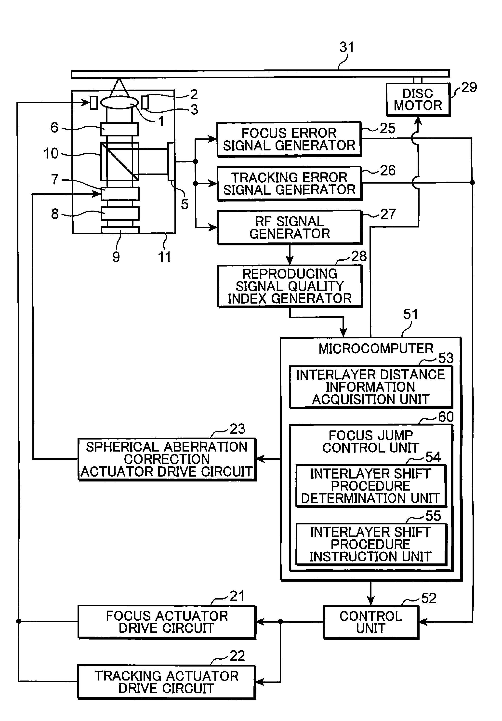
[0075]FIG. 1 is a block diagram depicting a configuration of an optical disc apparatus according to Embodiment 1 of the present invention.

[0076]The optical disc apparatus in FIG. 1 has an optical pickup 11, focus actuator drive circuit 21, tracking actuator drive circuit 22, spherical aberration correction actuator drive circuit 23, focus error signal generator 25, tracking error signal generator 26, RF signal generator 27, reproducing signal quality index generator 28, disc motor 29, microcomputer 51 and control unit 52. The optical pickup 11 has an objective lens 1, focus actuator 2, tracking actuator 3, light receiving unit 5, ¼ wavelength plate 6, spherical aberration correction unit 7, collimator lens 8, laser light source 9 and polarization beam splitter 10.

[0077]The optical pickup 11 irradiates a light beam onto an optical disc 31, and reads information recorded on the optical disc 31. Or the optical pickup 11 irradiates a light onto the optical disc 31, and records informati...

embodiment 2

[0161]An optical disc apparatus according to Embodiment 2 of the present invention will now be described.

[0162]In Embodiment 2, the spherical aberration correction amount upon execution of focus jump can be changed according to the respective interlayer distance of the two recording layers adjacent to the current recording layer in which focus control is performed.

[0163]FIG. 5 is a block diagram depicting an optical disc apparatus according to Embodiment 2 of the present invention.

[0164]The optical disc apparatus in FIG. 5 has an optical pickup 11, focus actuator drive circuit 21, tracking actuator drive circuit 22, spherical aberration correction actuator drive circuit 23, focus error signal generator 25, tracking error signal generator 26, RF signal generator 27, reproducing signal quality index generator 28, disc motor 29, microcomputer 51 and control unit 52. The optical pickup 11 has an objective lens 1, focus actuator 2, tracking actuator 3, light receiving unit 5, ¼ wavelengt...

embodiment 3

[0199]An optical disc apparatus according to Embodiment 3 of the present invention will now be described.

[0200]In Embodiment 1 and Embodiment 2, the spherical aberration correction operation and focus jump operation are independently operated, but in Embodiment 3, the focus jump operation is executed while continuing the spherical aberration correction operation without interrupting the spherical aberration correction operation.

[0201]FIG. 8 is a block diagram depicting an optical disc apparatus according to Embodiment 3 of the present invention.

[0202]The optical disc apparatus in FIG. 8 has an optical pickup 11, focus actuator drive circuit 21, tracking actuator drive circuit 22, spherical aberration correction actuator drive circuit 23, focus error signal generator 25, tracking error signal generator 26, RF signal generator 27, reproducing signal quality index generator 28, disc motor 29, microcomputer 51 and control unit 52. The optical pickup 11 has an objective lens 1, focus act...


PUM


Abstract

An optical disc apparatus has: a spherical aberration correction unit (7) which corrects the spherical aberration generated in a light spot on a recording layer; a control unit (52) which focuses a light beam on a predetermined recording layer, and shifts the focal point position of the light beam from the current recording layer to another recording layer; and a focus jump control unit (60) which controls correction of spherical aberration and shift of the focal point position based on the interlayer distance between the current recording layer and a recording layer which adjoins in a direction opposite to a direction of shifting the focal point position of the light beam. By this configuration, focus jump is stably executed.

Description

TECHNICAL FIELD[0001]The present invention relates to an optical disc apparatus which records and reproduces information by irradiating an optical beam onto a recording surface of an optical disc having by a plurality of layers, a focus control method for controlling focus of an optical beam which is irradiated onto an optical disc, and an integrated circuit for controlling focus of an optical beam which is irradiated onto an optical disc.BACKGROUND ART[0002]Available methods for increasing the recording capacity of an optical disc are: increasing density of an optical disc and using multi-recording layers.[0003]For example, in a Blu-ray disc, the recording capacity of one optical disc is increased to 50 GB by increasing the numerical aperture (NA) of an objective lens from 0.6 to 0.85 and decreasing the wavelength of the laser from 650 nm to 405 nm, so that density is increased, and by making the recording layer two layers.[0004]Recently in order to increase capacity even more, dev...

Claims


Application Information

Patent Timeline
IPC IPC(8): G11B7/00G11B7/135
CPCG11B7/08511G11B2007/0013G11B7/13922
Inventor SHIMAMOTO, TAKESHIYAMAMOTO, TAKEHARUKISHIMOTO, TAKASHI
Owner PANASONIC CORP
Why Eureka
Try Eureka