Eureka AIR delivers breakthrough ideas for toughest innovation challenges, trusted by R&D personnel around the world.

Method for NOx Reduction

a nox and reduction method technology, applied in the direction of engines, machines/engines, mechanical equipment, etc., can solve the problems of degrading the effectiveness of scr catalysts in treating nox emissions, reducing the efficiency of scr catalysts, etc., to achieve the effect of reducing engine performan

Active Publication Date: 2011-03-24
FORD GLOBAL TECH LLC
View PDF20 Cites 18 Cited by
  • Summary
  • Abstract
  • Description
  • Claims
  • Application Information

AI Technical Summary

Benefits of technology

[0002]Liquid reductant, one example of which is urea, may be injected into an engine's exhaust for use in an SCR catalyst. During low exhaust temperatures (due to, for example, light engine loads and low engine speeds during urban driving) reductant may be slower to evaporate and accumulate within the exhaust, leading to the formation of deposits (e.g., urea deposits) in the exhaust which may degrade engine performance. To reduce such deposits, lower doses of reductant may be injected and a disperser device may be used to break up droplets of injected reductant in the exhaust stream.
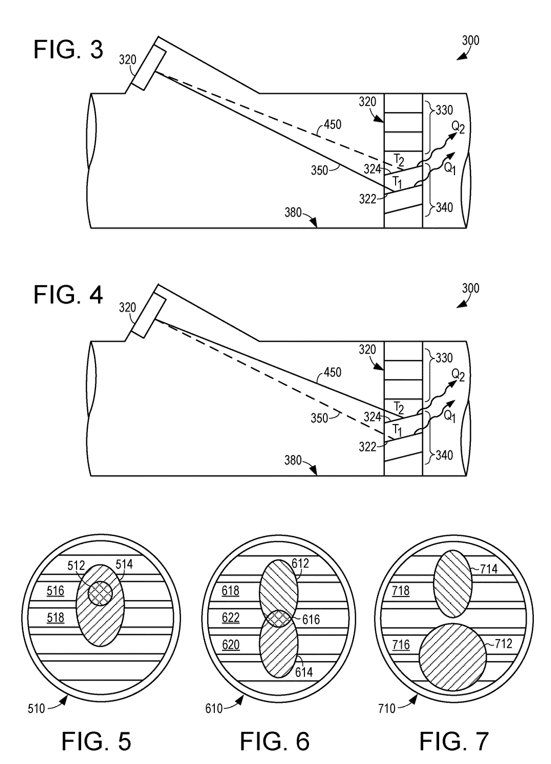
[0005]One advantage of such an approach is that heat transfer from exhaust flow to the disperser device may be utilized to increase vaporization of reductant, while compensating for the temperature gradients across the disperser device. For example, in the method described above, the second location may include higher temperature portions of the disperser device, the higher temperature portions causing increased evaporation of the reductant. Further, during transient engine conditions (such as increasing engine load or increasing engine speed) the second location may include little or none of the first location, leading to further heating of the reductant, and thus increased vaporization.

Problems solved by technology

During low exhaust temperatures (due to, for example, light engine loads and low engine speeds during urban driving) reductant may be slower to evaporate and accumulate within the exhaust, leading to the formation of deposits (e.g., urea deposits) in the exhaust which may degrade engine performance.
Injecting a decreased amount of reductant may degrade the SCR catalyst's effectiveness at treating NOx emissions.
What is more, a disperser device may not sufficiently increase urea evaporation for light engine loads and higher injection doses.
Further still, during changes in engine load, such as during vehicle acceleration from a slow speed, insufficient reductant may be provided at the SCR catalyst to treat NOx emissions, exacerbating the above described problems.
Further, during transient engine conditions (such as increasing engine load or increasing engine speed) the second location may include little or none of the first location, leading to further heating of the reductant, and thus increased vaporization.

Method used


Image

  • Method for NOx Reduction
  • Method for NOx Reduction
  • Method for NOx Reduction

Examples


Embodiment Construction

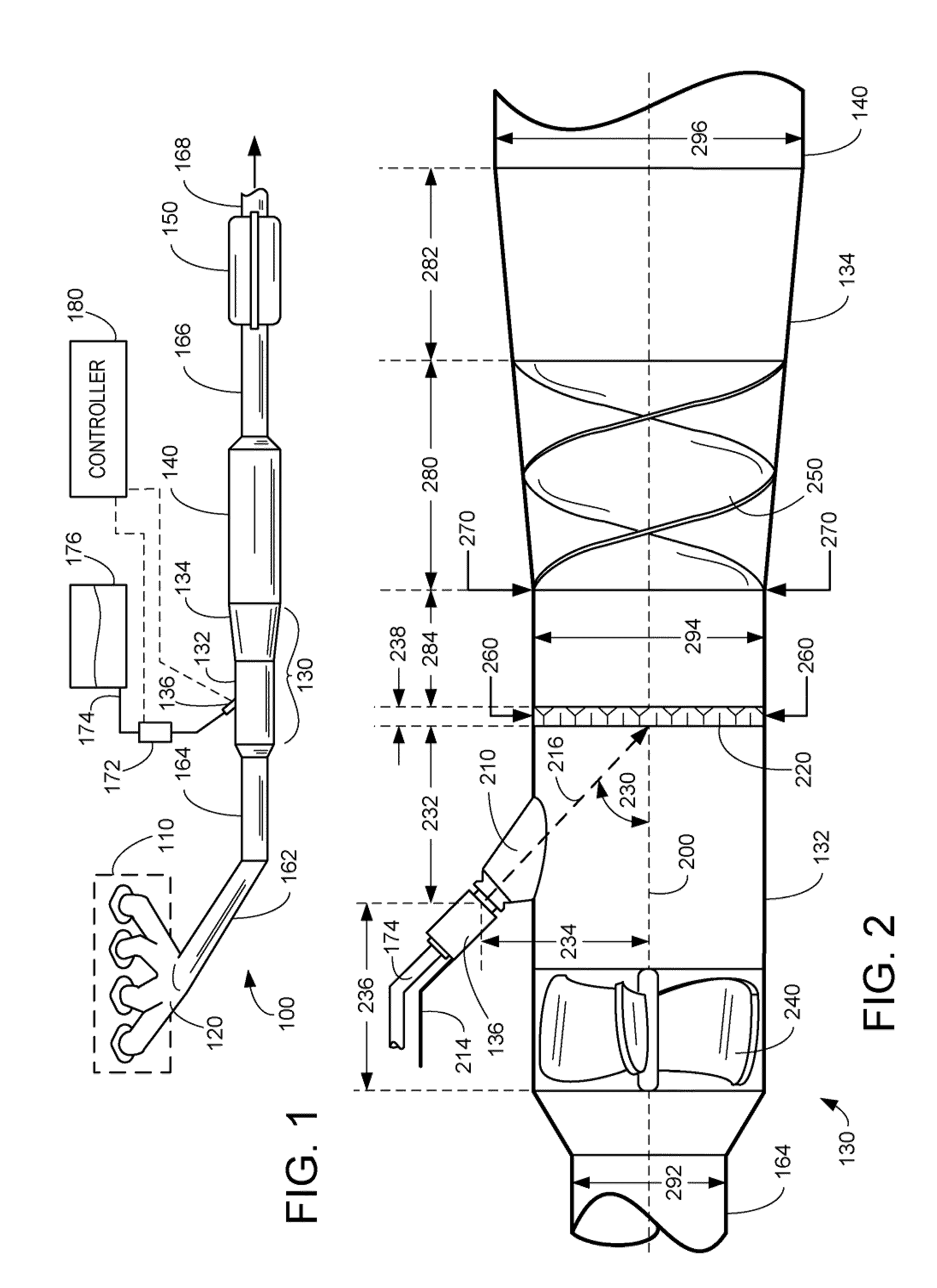
[0016]FIG. 1 illustrates an exhaust system 100 for transporting exhaust gases produced by internal combustion engine 110. As one non-limiting example, engine 110 includes a diesel engine that produces a mechanical output by combusting a mixture of air and diesel fuel. Alternatively, engine 110 may include other types of engines such as gasoline burning engines, among others. In some embodiments, engine 110 may be configured in a propulsion system for a vehicle. While exhaust system 100 may be applicable to stationary applications, it should be appreciated that exhaust system 100 as described herein, is particularly adapted for vehicle applications, particularly where geometric limitations limit the mixing region of the exhaust gases and reductant.

[0017]Exhaust system 100 may include one or more of the following: an exhaust manifold 120 for receiving exhaust gases produced by one or more cylinders of engine 110, a mixing region 130 arranged downstream of exhaust manifold 120 for rece...


PUM


Abstract

The present application relates to mitigating NOx emissions, and more particularly, to vehicles including a selective catalytic reduction (SCR) system in the exhaust of a diesel or gasoline engine. In one example a method includes temporarily increasing a liquid reductant dosing value injected by an injector from a first dosing value to a second dosing value, the temporary increase in response to a change from injecting liquid reductant onto a first impact location on a disperser device to injecting onto a second impact location on the disperser device.

Description

TECHNICAL FIELD[0001]The present application relates to mitigating NOx emissions, and more particularly, to vehicles including a selective catalytic reduction (SCR) system in the exhaust of a diesel or gasoline engine.BACKGROUND AND SUMMARY[0002]Liquid reductant, one example of which is urea, may be injected into an engine's exhaust for use in an SCR catalyst. During low exhaust temperatures (due to, for example, light engine loads and low engine speeds during urban driving) reductant may be slower to evaporate and accumulate within the exhaust, leading to the formation of deposits (e.g., urea deposits) in the exhaust which may degrade engine performance. To reduce such deposits, lower doses of reductant may be injected and a disperser device may be used to break up droplets of injected reductant in the exhaust stream.[0003]The inventors herein have recognized issues with the above described approaches. Injecting a decreased amount of reductant may degrade the SCR catalyst's effecti...

Claims


Application Information

Patent Timeline
IPC IPC(8): F01N3/20
CPCF01N3/2066F01N2240/20Y02T10/24F01N2610/1453F01N2610/02Y02T10/12Y02A50/20
Inventor ZIMMERMAN, BRET ALANLEVIN, MICHAELBOGEMA, JOHN PAULSHAIKH, FURQAN ZAFAR
Owner FORD GLOBAL TECH LLC
Why Eureka
Eureka Blog
Learn More