Eureka AIR delivers breakthrough ideas for toughest innovation challenges, trusted by R&D personnel around the world.

Method and system for measuring position on surface capacitance touch panel using a flying capacitor

a capacitance touch panel and surface technology, applied in the field of touchpad technology, can solve the problems of affecting the accuracy of touch panels b>10/b>, and the system is very susceptible to stray capacitan

Inactive Publication Date: 2011-03-17
CIRQUE CORPORATION
View PDF6 Cites 11 Cited by
  • Summary
  • Abstract
  • Description
  • Claims
  • Application Information

AI Technical Summary

Benefits of technology

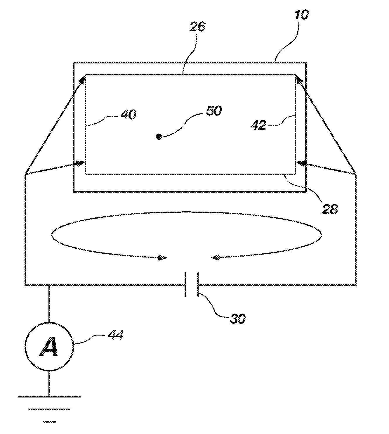
[0012]In a first embodiment, the present invention is a touch panel having a substantially even coating of a conductive material on a non-conductive substrate and then covering the conductive material with a dielectric material, wherein a novel current measuring circuit reduces the effect of stray capacitance on the accuracy of a current measurement so that the relative position of an object on the touch panel can be determined using simple ratio equations.

Problems solved by technology

Because the current is so small, the system is very susceptible to stray capacitance.
Thus, the accuracy of touch panels 10 is often an issue.

Method used


Image

  • Method and system for measuring position on surface capacitance touch panel using a flying capacitor
  • Method and system for measuring position on surface capacitance touch panel using a flying capacitor
  • Method and system for measuring position on surface capacitance touch panel using a flying capacitor

Examples


Embodiment Construction

[0018]Reference will now be made to the drawings in which the various elements of the present invention will be given numerical designations and in which the invention will be discussed so as to enable one skilled in the art to make and use the invention. It is to be understood that the following description is only exemplary of the principles of the present invention, and should not be viewed as narrowing the claims which follow.

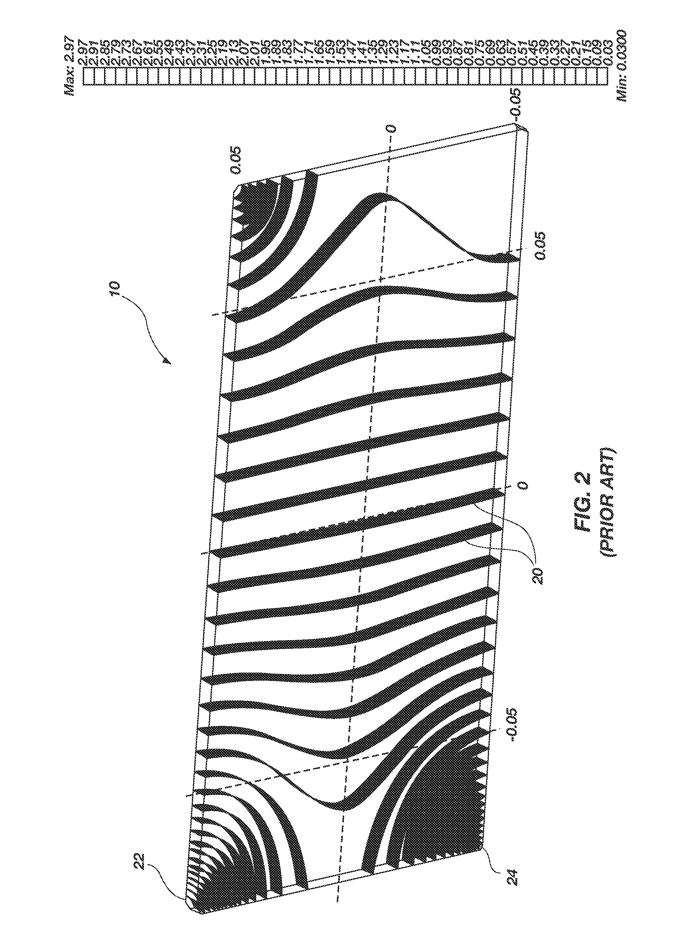
[0019]FIG. 2 shows the surface of a touch panel 10 as found in the prior art. The lines 20 are indicative of the voltage gradient that is produced across the surface of the touch panel when a voltage is applied at two corners of the surface. For example, the voltage is applied at corners 22 and 24 resulting in the constant voltage gradient shown. There is significant distortion of the voltage gradient lines 20 which is common to many touch panels 10.

[0020]FIG. 3 is a perspective view of a touch panel 10 that is made in accordance with the principles of the ...


PUM


Abstract

A touch panel having a substantially even coating of a conductive material on a non-conductive substrate and then covering the conductive material with a dielectric material, wherein a novel current measuring circuit reduces the effect of stray capacitance on the accuracy of a current measurement so that the relative X and Y position of an object on the touch panel can be determined using simple ratio equations.

Description

CROSS REFERENCE TO RELATED APPLICATIONS[0001]This document claims priority to, and incorporates by reference all of the subject matter included in the provisional patent application docket number 4455.CIRQ.PR, having Ser. No. 61 / 116,592 and filed on Nov. 20, 2008.BACKGROUND OF THE INVENTION[0002]1. Field of the Invention[0003]This invention relates generally to touchpad technology. More specifically, the present invention is a new method of determining the position of a pointing object on a surface capacitance touch panel.[0004]2. Description of Related Art[0005]A well-known touchpad technology uses a surface capacitance touch panel 10 as shown in FIG. 1. Such a touch panel 10 is a solid sheet of a conductive material 16 disposed on an insulating substrate 18 such as glass, with sensors 12 disposed at the corners. The traditional method of measuring the position of a pointing object 14 or the “touch position” on the surface capacitance touch panel 10 is to apply an AC signal on all ...

Claims


Application Information

Patent Timeline
Patent Type & Authority Applications(United States)
IPC IPC(8): G06F3/044
CPCG06F3/044G06F3/0444
Inventor BYTHEWAY, JARED G.PAULSEN, KEITH L.
Owner CIRQUE CORPORATION
Why Eureka
Eureka Blog
Learn More