
System for detecting operating errors in integrated circuits

Active Publication Date: 2011-03-10
STMICROELECTRONICS SRL
View PDF8 Cites 14 Cited by
  • Summary
  • Abstract
  • Description
  • Claims
  • Application Information

AI Technical Summary

Benefits of technology

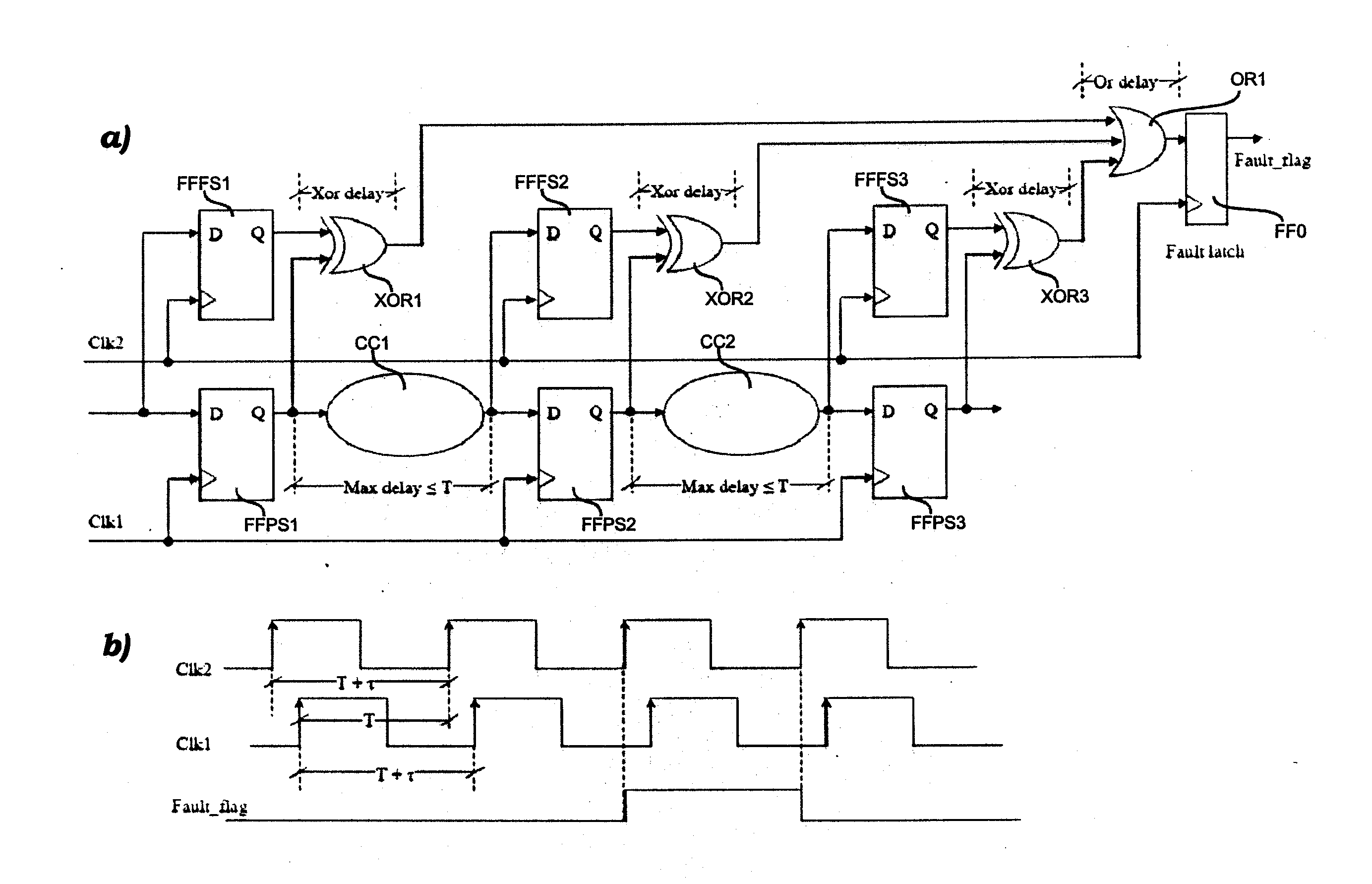
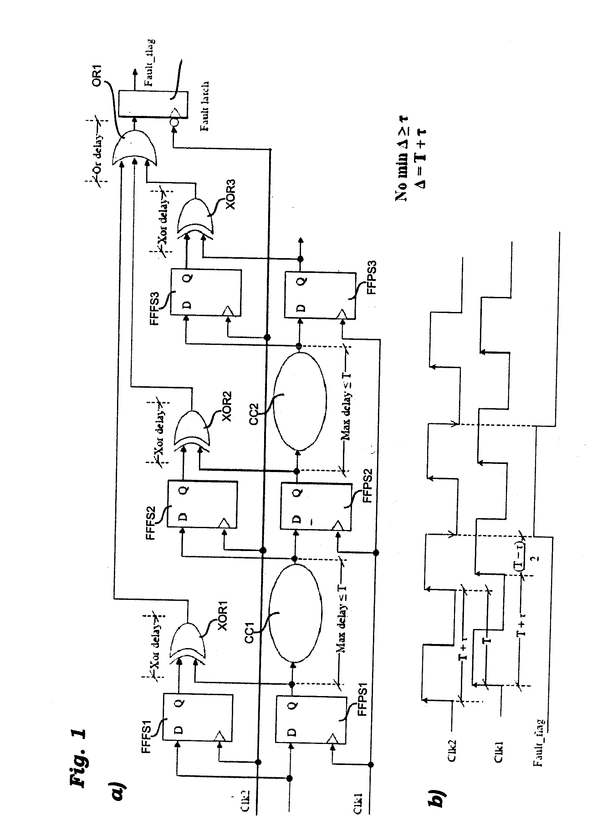
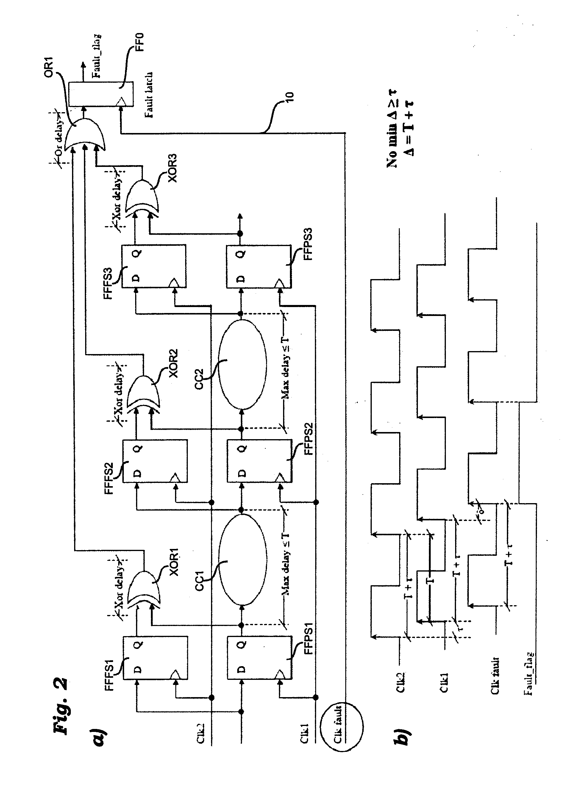
[0018]allowing a ports verification of the integrity of the circuit, avoiding the need for complete duplication thereof;
[0030]Various embodiments enable avoidance of the need to perform the same operation two or more times with the possibility of increasing the operating clock time according to the granularity of the desired control action.
[0033]Various embodiments present the main advantage linked to the possibility of varying the granularity of the action of error detection, without any circuit modifications.
[0038]Various embodiments are able to achieve the advantages outlined above without any appreciable increase in the total area of the system, enabling in any case preservation of the performance in the presence of an error, preventing the operating clock period from increasing according to the level of granularity required, whereas other (simpler) embodiments enable preservation of the performance in the presence of an error but with the clock period that increases according to the required level of granularity.

Problems solved by technology

Computers with a high degree of fault tolerance can consequently be rather costly and complex to design.
The transient failures or faults are temporary ones (i.e., non-permanent ones) that are likely to arise in a circuit during its operation on account of the effect of various internal and external sources of noise.
In particular, in digital systems these failures or faults can be produced by internal sources of noise, such as for example supply transients, phenomena of capacitive and inductive diaphony, or else by external sources of noise, such as for example the effect of particles or cosmic rays (such as precisely alpha particles).
Consequently, an effect of noise that initially would not be particularly harmful for operation of a complex digital circuit can become an important source of disturbance after being propagated through the logic gates of the circuit (for example NAND, NOR gates, or logic inverters).

Method used


Image

  • System for detecting operating errors in integrated circuits
  • System for detecting operating errors in integrated circuits
  • System for detecting operating errors in integrated circuits

Examples


Embodiment Construction

[0047]Illustrated in the ensuing description are various specific details aimed at providing an in-depth understanding of the embodiments. The embodiments may be implemented without one or more of the specific details, or with other methods, components, materials, etc. In other cases, known structures, materials or operations are not shown or described in detail so that various aspects of the embodiments will not be obscured.

[0048]The reference to “one embodiment” in the framework of this description is meant to indicate that a particular configuration, structure, or characteristic described in relation to the embodiment is included in at least one embodiment. Hence, phrases such as “in one embodiment”, that may be present in various points of the present description, do not necessarily refer to one and the same embodiment. Furthermore, particular conformations, structures, or characteristics can be adequately combined in one or more embodiments.

[0049]The references used herein are ...


PUM


Abstract

Errors induced by noise pulses in digital electronic circuits clocked with a clock signal are detected by providing at least one additional clock signal offset in time with respect to the clock signal by a given interval, and performing for at least one component of the circuit a comparison of correspondence between two versions of one and the same signal. The comparison is clocked by the additional clock signal and the absence of correspondence between the two versions of said signal identifies an error induced in the circuit by a noise pulse.

Description

RELATED APPLICATION[0001]The present application claims priority of Italian Patent Application No. TO2009A000629 filed Aug. 7, 2009, which is incorporated herein in its entirety by this reference.FIELD OF THE INVENTION[0002]The present invention relates to techniques for detecting operating errors in electronic systems, sometimes referred to fault tolerance techniques. The present application has particular utility in correcting operating errors due to noise pulses in electronic systems.BACKGROUND[0003]Various fields of application of integrated circuits (e.g., applications in biomedical, automotive and avionics sectors) require the corresponding systems to operate in “zero failure” conditions, i.e., prove practically immune in regard to disturbance, such as, for example, impulsive noise due to external radiation (cosmic rays, microwaves, ultraviolet rays, electromagnetic fields of various nature, etc.) and to phenomena of internal migration of energy and of coupling between conduct...

Claims


Application Information

Patent Timeline
IPC IPC(8): G06F11/00
CPCG06F11/0751H03K19/007G06F11/1629G06F11/1608
Inventor PAPPALARDO, FRANCESCONOTARANGELO, GIUSEPPEGUIDETTI, ELIO
Owner STMICROELECTRONICS SRL
Learn More