
Surface mount resistor

Active Publication Date: 2011-03-10
CYNTEC
View PDF6 Cites 16 Cited by
  • Summary
  • Abstract
  • Description
  • Claims
  • Application Information

AI Technical Summary

Benefits of technology

[0007]Therefore, in order to solve aforementioned problems, the present invention is to provide a surface mount resistor which has a better heat dissipation effect and a better thermal stability of the resistance value.

Problems solved by technology

Some performances of traditional chip resistor, such as temperature coefficient of resistance (TCR), have gradually been unable to satisfy the requirement of high stability, thus, causing its limitation in terms of application.
However, during the stamping process, surfaces of the resistor body and the heat-dissipation body will generate deckle edges or protrusions, which probably penetrate the pressed or adhesive layer (its thickness is about 30 μm) during the combination of the resistor body and the heat-dissipation body, causing a short circuit, because of the contact between the resistor body and the heat-dissipation body, so the resistance value of the resistor can't fulfill preset requirement.
Furthermore, since the current sensing resistor adopts two rectangular heat-dissipation bodies, which are symmetrical to two sides of the resistor body, only heat at two sides of the resistor body can be carried away, while the heat at the central portion with higher temperature can't be dissipated.
This kind of design has imposed a great limitation on carrying away the heat generated in resistor body, which limits the promotion of the operational power thereof.

Method used


Image

  • Surface mount resistor
  • Surface mount resistor
  • Surface mount resistor

Examples


Embodiment Construction

[0021]In cooperation with attached drawings, the technical contents and detailed description of the present invention are described thereinafter according to a number of embodiments, not used to limit its executing scope. Any equivalent variation and modification made according to appended claims is all covered by the claims claimed by the present invention.

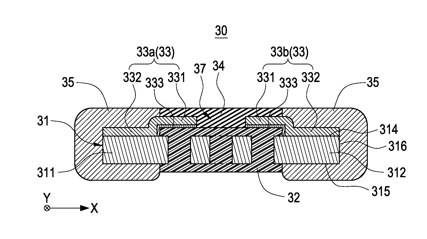
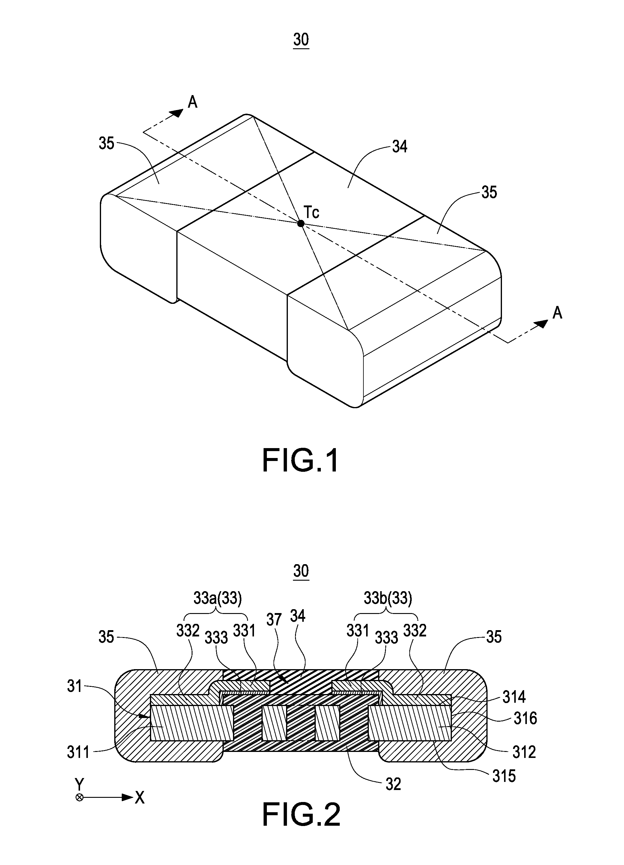
[0022]As shown in FIG. 1 and FIG. 2, a surface mount resistor 30 according to the first embodiment of the invention is shown. The surface mount resistor 30, for example a current sensing resistor have a low resistance value, includes a resistance body 31, a first protective layer 32, at least one heat-transfer layer 33, a second protective layer 34 and two electrode layers 35.

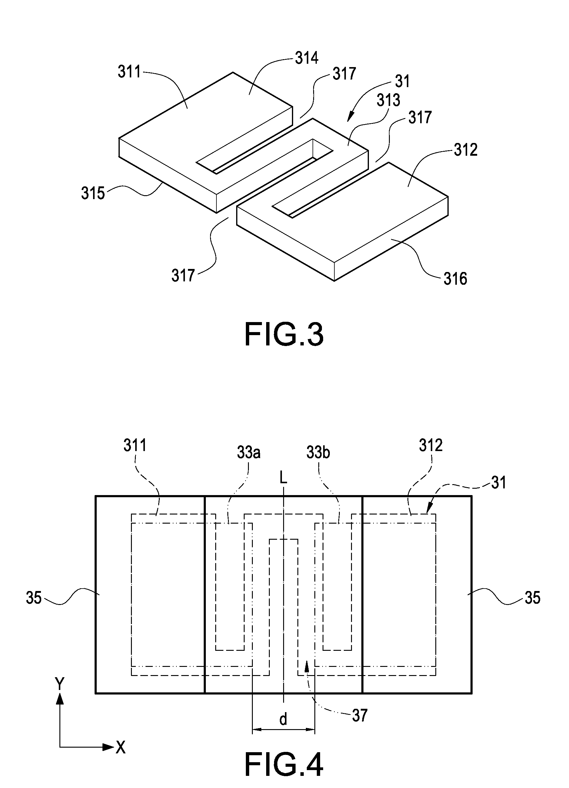
[0023]As shown in FIG. 3, the resistance body 31 has a first end portion 311, a second end portion 312 opposite to the first end portion 311 and a central portion 313 arranged between the first end portion 311 and the second end portion 312. The resistance b...


PUM


Abstract

A surface mount resistor includes a resistance body, a first protective layer, a heat-transfer layer, a second protective layer and two electrode layers. The resistance body has a first end portion, a second end portion and a central portion between the first end portion and the second end portion. The first protective layer is disposed on the central portion of the resistance body, and the first end portion and the second end portion are exposed. The heat-transfer layer is plated on at least part of the resistance body. The second protective layer is disposed on at least part of the heat-transfer layer. The electrode layers are respectively arranged on the first end portion and the second end portion, and electrically connected with the heat-transfer layer.

Description

BACKGROUND OF THE INVENTION[0001]1. Field of the Invention[0002]The present invention relates to an electronic component, and more particularly, to a surface mount resistor for current sensing.[0003]2. Description of Prior Art[0004]Following continuous progress of electronic circuit technology, stability requirement of resistance value of resistor has been increased day by day. Some performances of traditional chip resistor, such as temperature coefficient of resistance (TCR), have gradually been unable to satisfy the requirement of high stability, thus, causing its limitation in terms of application.[0005]In order to promote thermal stability of resistor, Taiwan Patent Publication No. 200830333 and 200830334 have proposed a current sensing resistor, in which a heat-dissipation body with high performance is formed on a surface of a resistor body to dissipate the heat generated therefrom, such that the object of promoting the operational power of the current sensing resistor is achie...

Claims


Application Information

Patent Timeline
IPC IPC(8): H01C1/034
CPCH01C17/02H01C17/065H01C17/006H01C7/13H01C7/003
Inventor CHEN, CHING-FENGSHIH, KUN-HONGLIN, YEN-TINGYEH, YIN-TIEN
Owner CYNTEC
Learn More