
Reflection-Reducing Interference Layer System and Method for Producing It

a technology of interference layer and interference layer, which is applied in the field of reflection-reducing interference layer system, can solve the problem that hard materials cannot be readily employed, and achieve the effect of reducing the number of interference layers

Active Publication Date: 2011-03-03
FRAUNHOFER GESELLSCHAFT ZUR FOERDERUNG DER ANGEWANDTEN FORSCHUNG EV
View PDF11 Cites 33 Cited by
  • Summary
  • Abstract
  • Description
  • Claims
  • Application Information

AI Technical Summary

Benefits of technology

[0009]One aspect of the invention is an improved reflection-reducing interference layer system which is distinguished by low reflection over a wide wavelength and incident angle range and, in particular, can also be used on materials such as glass or quartz. A further aspect is to specify a comparatively simple and cost-effective method for producing the system.
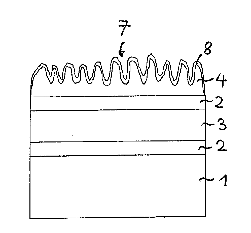
[0019]The nanostructured layer is preferably the covering layer of the interference layer system. In this case, the low refractive index of the nanostructured layer has a particularly advantageous effect since the difference in refractive index with respect to the surrounding medium, for example, air, is reduced in this way, with the result that particularly low reflection of the interference layer system can be obtained.
[0021]The number of alternating layers of the interference layer system is preferably at least five, particularly preferably at least seven. A high number of alternating layers advantageously makes it possible to obtain particularly low reflection in a large spectral range.
[0029]The thin layer advantageously has a thickness of just 2 nm or less. Applying this thin layer before carrying out the plasma etching process has the advantage that the thin layer acts as an initial layer for the plasma etching process and thus makes it possible to produce a nanostructure even in materials in which this would be possible only with difficulty or not at all without the prior application of the thin layer.

Problems solved by technology

The production of nanostructures by means of a plasma etching method can be employed in the case of plastic surfaces, for example, composed of PMMA or other thermoplastics and also soft resists, but cannot readily be employed for harder materials.

Method used


Image

  • Reflection-Reducing Interference Layer System and Method for Producing It
  • Reflection-Reducing Interference Layer System and Method for Producing It
  • Reflection-Reducing Interference Layer System and Method for Producing It

Examples


Embodiment Construction

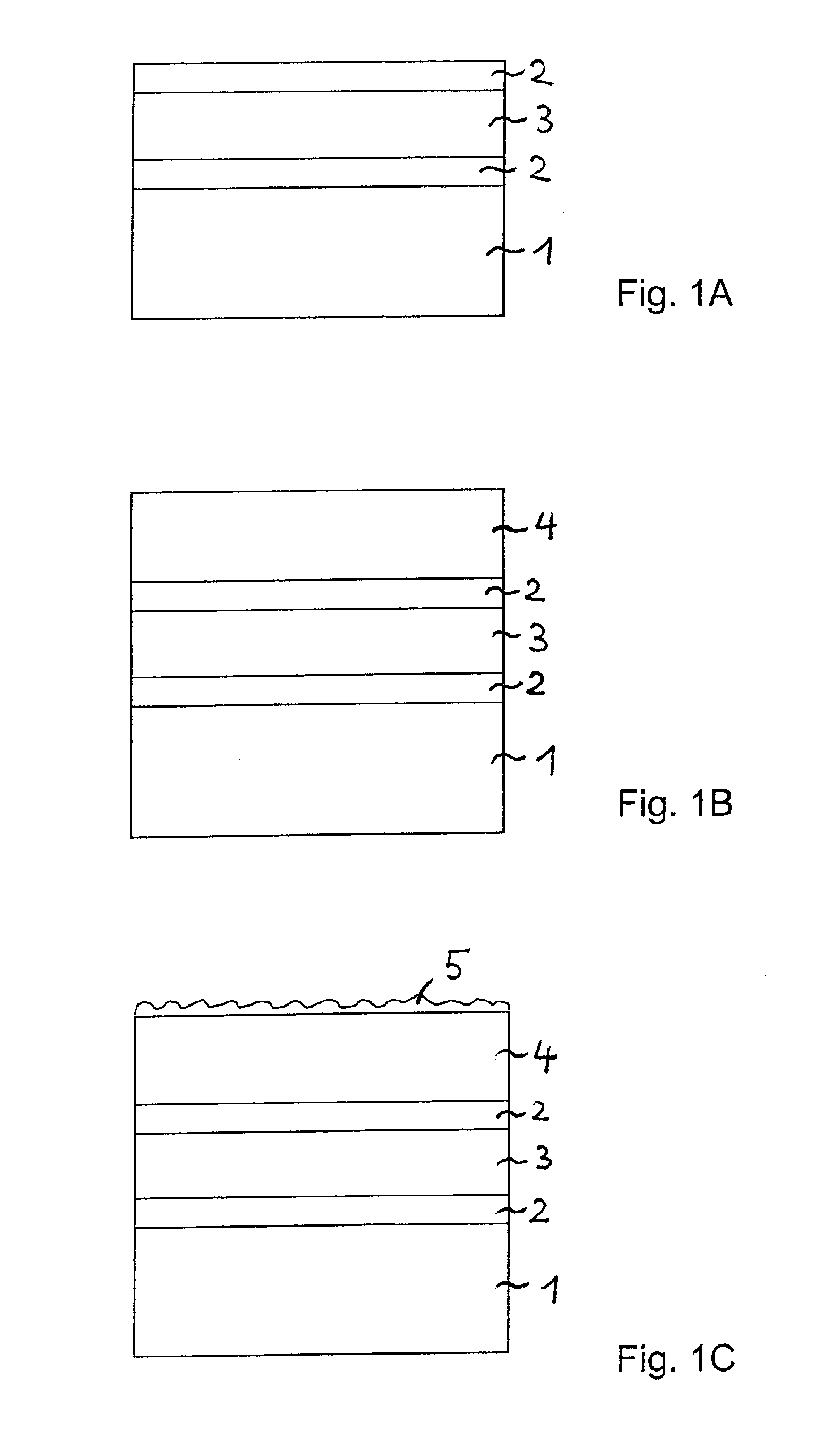
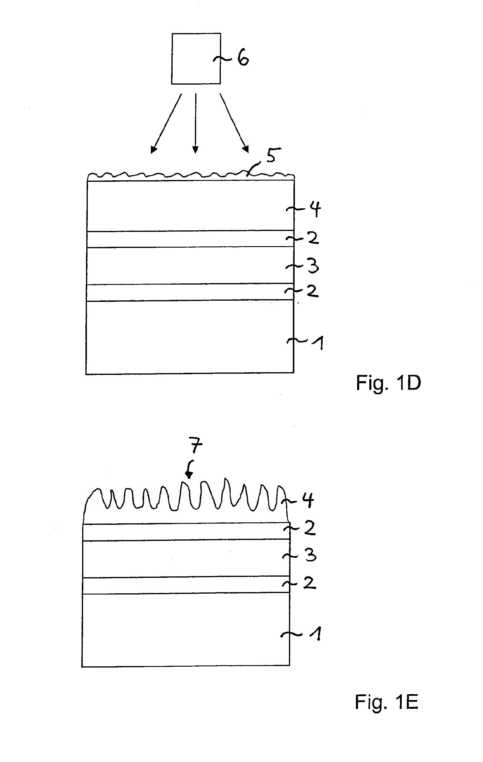
[0041]Identical or identically acting constituent parts are in each case provided with the same reference symbols in the figures. The illustrated constituent parts and also the size relationships of the constituent parts among one another should not be regarded as true to scale.

[0042]In the first intermediate step of a method for producing a reflection-reducing interference layer system, as illustrated in FIG. 1A, a plurality of layers 2, 3 having different refractive indices have been applied to a substrate 1. The substrate 1 can be, in particular, an optical element whose surface is intended to be antireflection-coated by the application of a reflection-reducing interference layer system. By way of example, the substrate 1 can be a lens such as, for example, a spectacle lens or the surface of a display.

[0043]The substrate 1 can be, in particular, a substrate composed of glass or quartz, but it can also be formed from a plastic. The substrate 1 can have a refractive index of n=1.5,...


PUM

PropertyMeasurementUnit
Thicknessaaaaaaaaaa
Thicknessaaaaaaaaaa
Thicknessaaaaaaaaaa

Abstract

A reflection-reducing interference layer system is disclosed, which has at least three alternating layers having different refractive indices. At least one nanostructured layer comprising an organic material or an organic-inorganic hybrid material is applied to the alternating layers. With the interference layer system, it is possible to obtain very low reflection over a wide wavelength and incident angle range.

Description

[0001]This application is a continuation of co-pending International Application No. PCT / EP2009 / 054253, filed Apr. 8, 2009, which designated the United States and was not published in English, and which claims priority to German Application No. 10 2008 018 866.2, filed Apr. 15, 2008, both of which applications are incorporated herein by reference.TECHNICAL FIELD[0002]The invention relates to a reflection-reducing interference layer system and a method for producing it.BACKGROUND[0003]For the antireflection coating of surfaces, in particular of optical elements or displays, use is usually made of reflection-reducing interference layer systems containing a plurality of alternating layers composed of high refractive index and low refractive index materials. MgF2 with n=1.38 is currently used as material having a particularly low refractive index in the visible spectral range. The antireflection effect of conventional dielectric layer systems could be improved if materials having a lowe...

Claims


Application Information

Patent Timeline
IPC IPC(8): G02B1/11B05D3/10B05D5/06B82Y20/00B82Y40/00
CPCG02B1/111G02B1/12G02B1/118G02B1/14
Inventor SCHULZ, ULRIKEMUNZERT, PETERKAISER, NORBERT
Owner FRAUNHOFER GESELLSCHAFT ZUR FOERDERUNG DER ANGEWANDTEN FORSCHUNG EV
Learn More