Screw Assembly and Method
a technology of screw and assembly method, which is applied in the field of orthopedic surgical implant assembly, can solve the problems of reducing fatigue resistance, conventional polyaxial systems typically cannot lock into the desired position, and surgical procedures treating spinal injuries are among the most complex and challenging surgeries for both patients and surgeons, and achieves the effect of high material hardness and compressive yield strength
- Summary
- Abstract
- Description
- Claims
- Application Information
AI Technical Summary
Benefits of technology
Problems solved by technology
Method used
Image
Examples
first embodiment
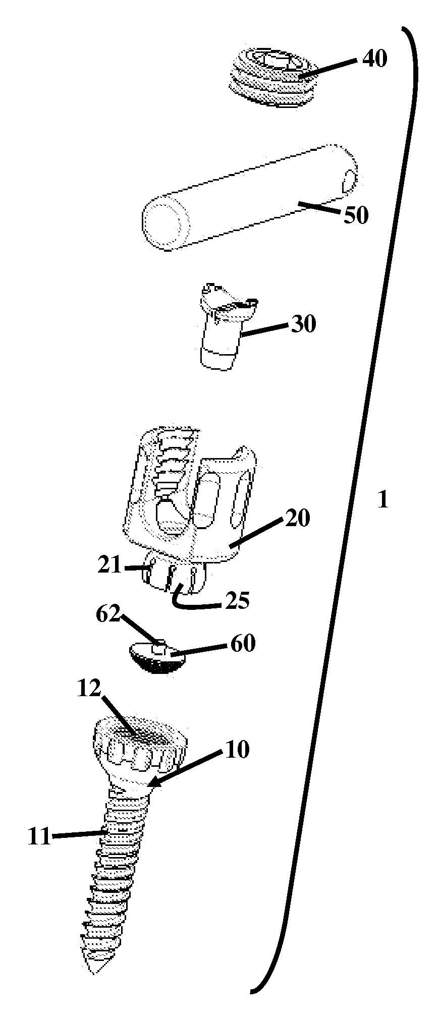
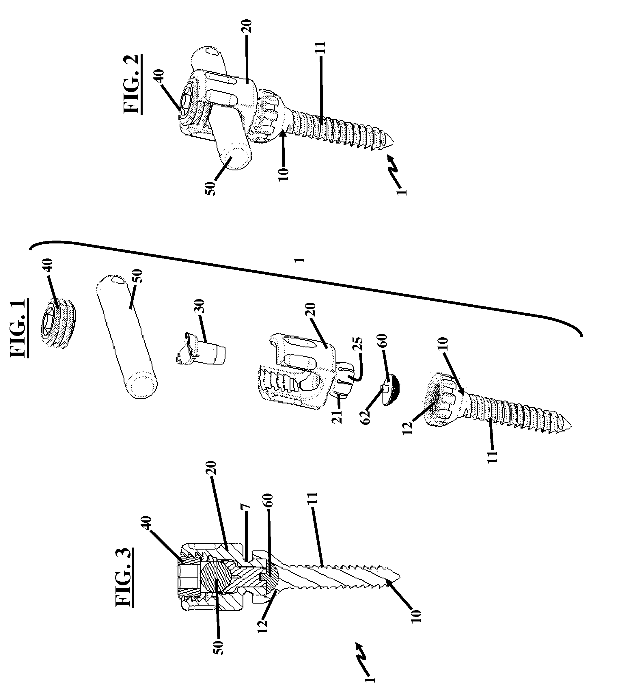
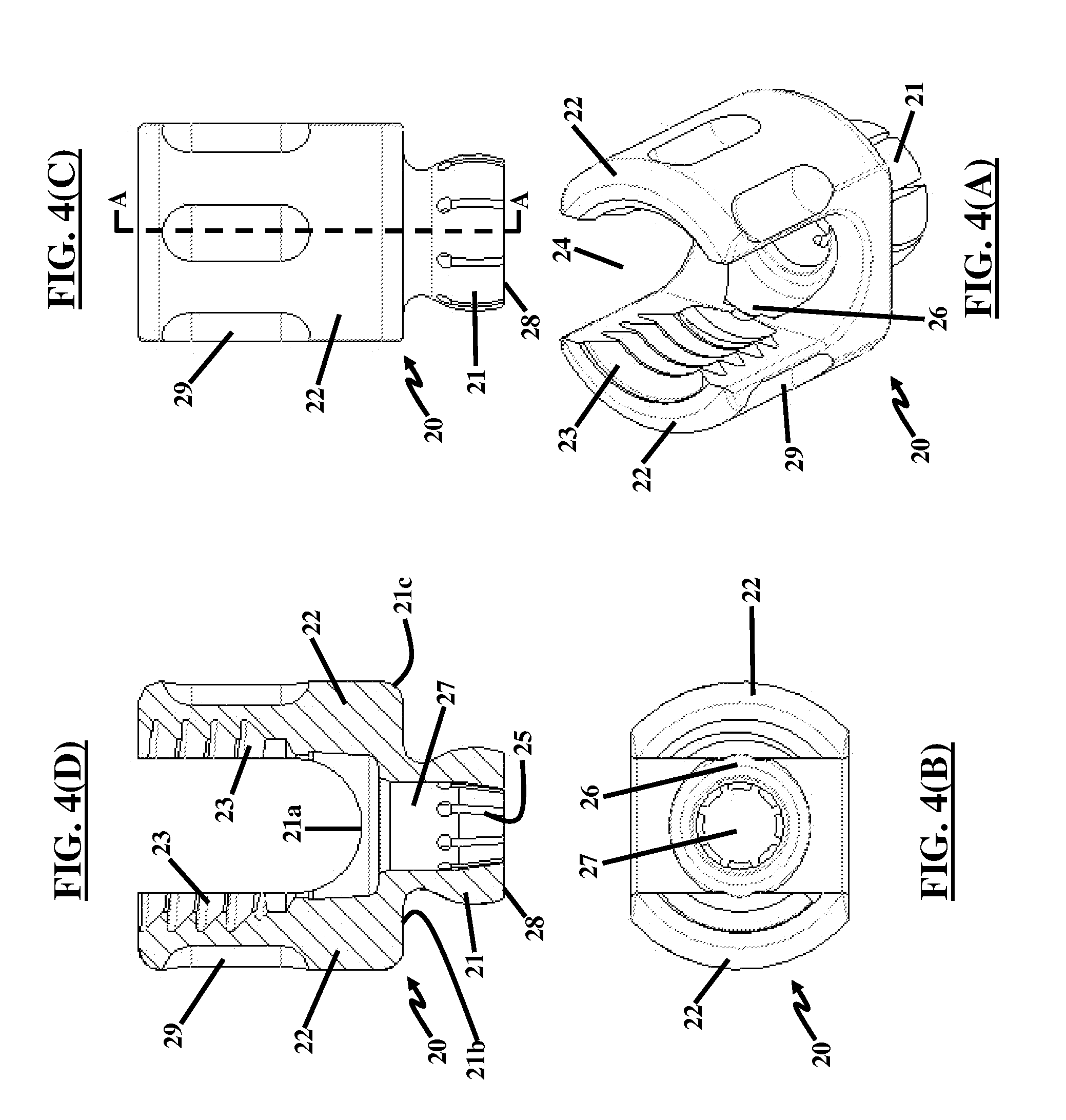
[0050]FIGS. 1 through 3, with reference to FIGS. 4(A) through 4(D), illustrate a pedicle screw assembly 1 herein. The screw assembly 1 comprises a fixator component (e.g., a bone screw) 10 having a threaded end 11 for engaging a bone (not shown) and a concave female socket 12 for engaging and receiving the coupling member 20. In another embodiment, the fixator component may be embodied as a hook mechanism (not shown).
[0051]As implemented, the coupling member 20 is first snapped into place in the fixator component 10 as shown in FIG. 2. Then, as shown in FIG. 3 the saddle connection pin 30 snaps into place in the lower base portion 25 of the coupling member 20, which includes a groove 26 (not shown in FIG. 1, but is best seen in FIGS. 4(A) through 4(D)) for receiving the saddle connection pin 30. In the manufacturing process, once the saddle connection pin 30 snaps into place, the screw assembly 1 is prepared for ultra sonic cleaning to remove any impurities and subsequently may be ...
second embodiment
[0066]FIGS. 10(A) and 10(B), with reference to FIGS. 1 through 9(D), illustrate a pedicle screw assembly 5 herein. The screw assembly 5 comprises a fixator component (e.g., a bone screw) 10 having a threaded end 11 for engaging a bone (not shown) and a concave female socket 12 for engaging and receiving the coupling member 20. In another embodiment, the fixator component may be embodied as a hook mechanism (not shown).
[0067]FIG. 10(B) also shows that the female spherical pocket 12 of the fixator component 10 has an undercut 7 to allow the coupling member 20 to pivot freely but not to disassemble once the expanding saddle connection pin 30 is inserted. The thread 11 of the fixator component 10 may be a multiple lead thread to allow faster insertion into a bone. This thread 11 may be tapered on the minor diameter while cylindrical on the major diameter to allow a new “bite” with every turn and to accommodate more thread depth towards the bottom of the fixator component 10 for the can...
PUM
 Abstract
Description
Claims
Application Information
 - R&D
- Intellectual Property
- Life Sciences
- Materials
- Tech Scout
- Unparalleled Data Quality
- Higher Quality Content
- 60% Fewer Hallucinations
Browse by: Latest US Patents, China's latest patents, Technical Efficacy Thesaurus, Application Domain, Technology Topic, Popular Technical Reports.
© 2025 PatSnap. All rights reserved.Legal|Privacy policy|Modern Slavery Act Transparency Statement|Sitemap|About US| Contact US: help@patsnap.com


