
Glass film laminate

a technology of glass film and laminate, applied in the field of glass film laminate, can solve the problems of glass substrate breakage, low flexibility, weak tensile stress of glass used for a substrate, etc., and achieve the effect of reducing close contact, and improving the easiness of handling glass film

Active Publication Date: 2011-02-24
NIPPON ELECTRIC GLASS CO LTD
View PDF15 Cites 48 Cited by
  • Summary
  • Abstract
  • Description
  • Claims
  • Application Information

AI Technical Summary

Benefits of technology

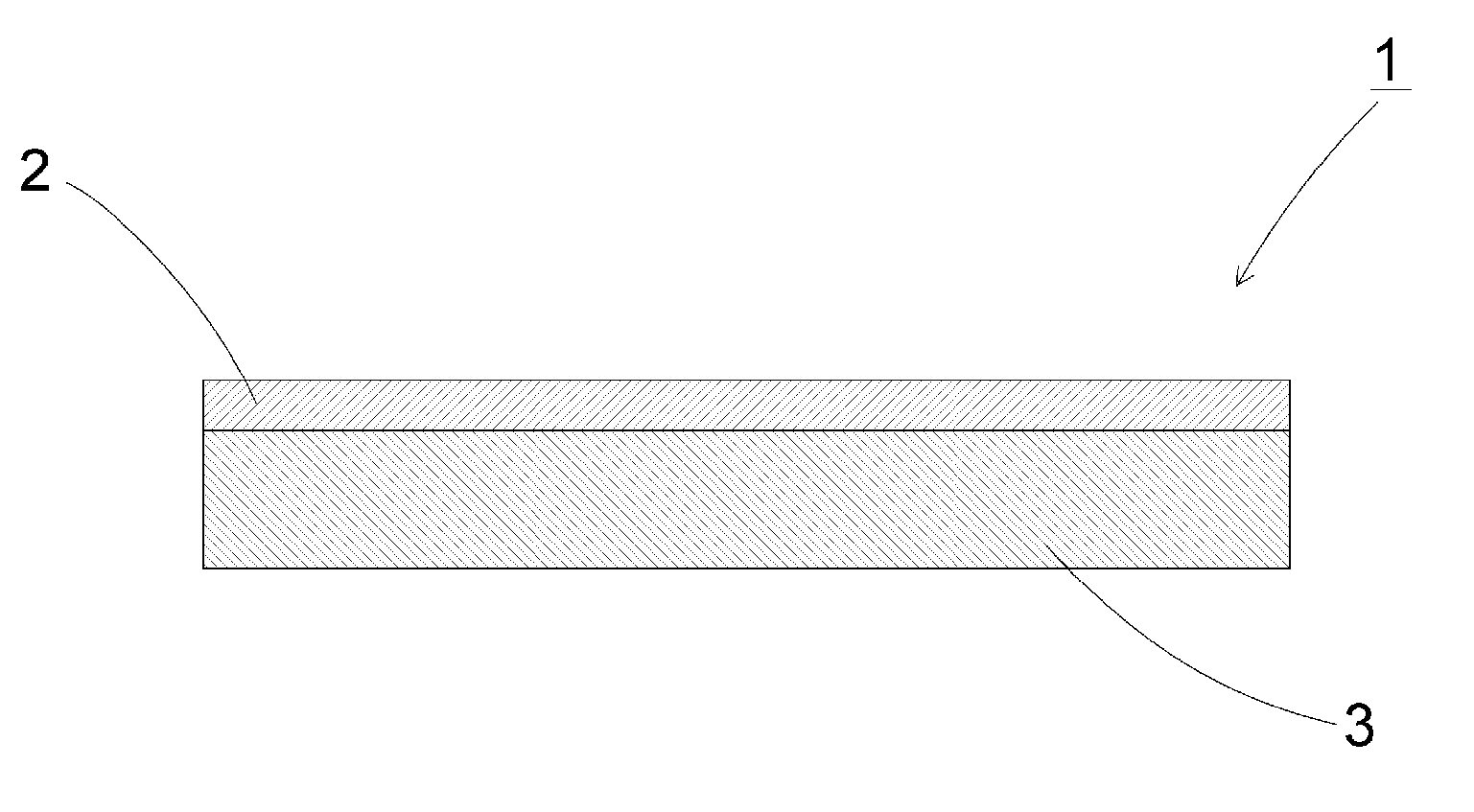
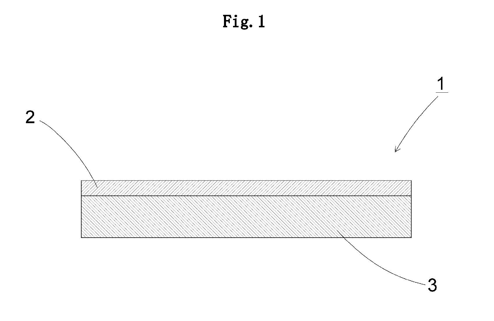
[0023]According to the invention claimed in claim 1, since the glass film laminate is constituted by the supporting glass and the glass film, the glass film laminate enhances handling easiness of the glass film when the glass film is subjected to treatments associated with production, and can prevent occurrence of problems such as a positioning error and displacement in patterning. The surface of the glass film and the surface of the supporting glass, which are brought into contact with each other, have a surface roughness Ra of 2.0 nm or less respectively, and the glass film and the supporting glass are brought into contact with each other with such the smooth surfaces. As a result, the glass film and the supporting glass are in a close contact, thereby, it is possible to laminate the glass film and the supporting glass firmly and stably without use of adhesive. No adhesive is used, and hence, when the glass film is incorporated into any of various devices after the treatments associated with production, peeling off even one portion of the glass film from the supporting glass enables easy subsequent peeling off the whole glass film from the supporting glass. In addition, the glass film is free from any remaining adhesive.
[0024]On the other hand, if the surface roughness Ra exceeds 2.0 nm, the close contact decreases. As a result, it is not possible to laminate the glass film and the supporting glass firmly without use of adhesive.
[0025]According to the invention claimed in claim 2, since the surface of the glass film and the surface of the supporting glass, which are brought into contact with each other, have a GI value of 1000 pcs / m2 or less respectively, the contacting surfaces of the glass film and supporting glass are clean, leading to undamaged activity of the surfaces. As a result, it is possible to laminate the glass film and the supporting glass more firmly and more stably without use of adhesive.
[0026]According to the invention claimed in claim 3, since the glass film has a thickness of 300 μm or less, even in an ultra-thin glass film, which is more difficult to handle and is easily involved in problems such as a positioning error and displacement in patterning, treatments associated with production can be easily carried out.
[0015]The invention according to claim 4 relates to a glass film laminate according to any one of claims 1 to 3, wherein the supporting glass has a thickness of 400 μm or more.
[0028]According to the invention claimed in claim 5, since the difference of thermal expansion coefficients between the glass film and the supporting glass at 30 to 380° C. falls within 5×10⁻⁷ / ° C., even when a heat treatment is carried out during treatments associated with production, a glass film laminate can hardly have a thermal warpage or the like.
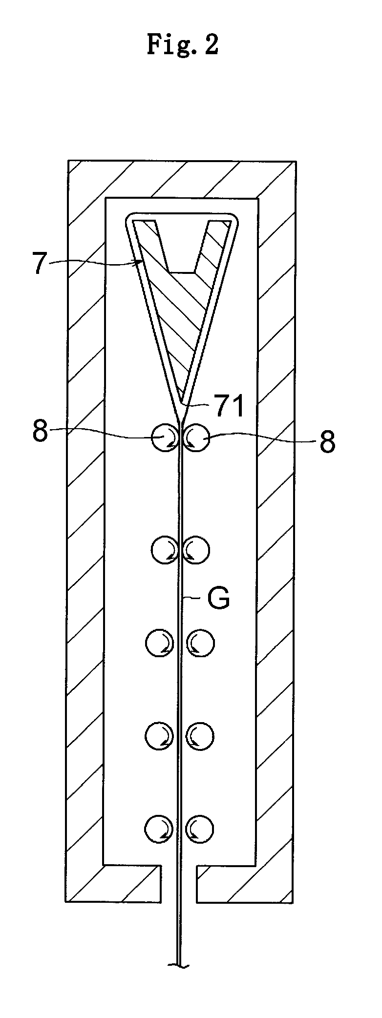
[0029]According to the invention claimed in claim 6, since the glass film and the supporting glass are formed by the overflow down-draw method, the surfaces thereof have extremely high in surface precision without being subjected to a polishing process. As a result, the glass film and the supporting glass can be laminated more firmly.
[0030]According to the invention claimed in claim 7, since the glass film and the supporting glass are laminated so that at least a part of an edge portion includes a step, in the case where the glass film protrudes from the supporting glass, it is possible to peel off the glass film and the supporting glass from each other more easily in a more secure manner. On the other hand, in the case where the supporting glass protrudes from the glass film, it is possible to properly protect an end portion of the glass film from striking, or the like.
[0031]According to the invention claimed in claim 8, since the peeling sheet member is interposed at a partial region of the contact portion between the glass film and the supporting glass, and the sheet member partially protrudes from the contact portion, it is possible to peel off the glass film and the supporting glass from each other more easily in a more secure manner while grasping the protruding portion of the sheet member.
[0032]According to the invention claimed in claim 9, since the supporting glass includes at least one through-hole formed at a position being outside of an effective surface of the glass film, when the glass film is peeled off from the supporting glass, it is possible to raise up the glass film only by injecting compressed air or inserting a pin or the like through the through-hole, resulting in easily starting peeling off the glass film.
[0033]According to the invention claimed in claim 10, since the glass film laminate includes a guide member for positioning the glass film on the supporting glass at the glass film side, it is possible to easily position the glass film with respect to the supporting glass when the glass film is laminated on the supporting glass.
[0034]According to the invention claimed in claim 11, since the guide member has a smaller thickness than the glass film, when the glass film laminate is subjected to a cleaning treatment as one of the treatments associated with production, it is possible to prevent a liquid from remaining on the surface of the glass film.

Problems solved by technology

However, glass used for a substrate is weak in tensile stress unlike a resin film, and hence is low in flexibility.
Thus, concentrarion of a tensile stress on a surface of a glass substrate by bending the glass substrate leads to the breakage of the glass substrate.
However, when a glass film is used as a glass substrate for these electronic devices, the glass film breaks due to a stress change even at a small amount, because glass is a brittle material.
Thus, there is a problem in that the handling of the glass film is very difficult, when the above-mentioned various treatments associated with electronic device production are carried out.
In addition, there is another problem in that a glass film having a thickness of 200 μm or less is rich in flexibility, and hence the positioning of the glass film is difficult when the treatments associated with production are carried out, so that displacement or the like in patterning may occur.
However, there is a problem in that when the resin film is finally peeled off from the laminate to provide a glass film solely, the glass film which is a brittle material is easy to break, and the pressure-sensitive adhesive substance remains on the glass film after the resin film is peeled off, causing contamination.
Further, there is a difference in thermal expansion coefficients of the resin film and the glass film, and hence, even in a case where a heat treatment is carried out at a relatively low temperature of around 200° C. as a treatment associated with production, there is a possibility in that thermal warpage, resin peeling, or the like may occur.
In addition, there is another problem in that displacement or the like easily occurs when the positioning and the patterning during treatments associated with production are carried out, because the resin film is also rich in flexibility.
However, even in the above-mentioned laminate, there has not yet been solved such a problem that a pressure-sensitive adhesive remains on the thin glass sheet after peeling off of the supporting glass.

Method used


Image

  • Glass film laminate
  • Glass film laminate
  • Glass film laminate

Examples


examples

[0071]Hereinafter, the glass film laminate of the present invention is described in detail based on examples, but the present invention is not limited to these examples.

[0072]A transparent glass sheet having a rectangular shape and having 250 mm in length, 250 mm in width, and 700 μm in thickness was used as a supporting glass. A glass film having 230 mm in length, 230 mm in width, and 100 μm in thickness was used as a glass film to be laminated on the supporting glass. Used for the supporting glass and the glass film was alkali-free glass manufactured by Nippon Electric Glass Co., Ltd. (Production name: OA-10G, thermal expansion coefficient at 30 to 380° C.: 38×10−7 / ° C.). The glass formed by the overflow down-draw method was used without polishing as it is, or by appropriately controlling amounts of polishing and chemical etching, to thereby control the surface roughness Ra. The surface roughness Ra of the contacting surface of each of the supporting glass and the glass film was m...


PUM

PropertyMeasurementUnit
Temperatureaaaaaaaaaa
Thicknessaaaaaaaaaa
Thicknessaaaaaaaaaa

Abstract

The glass film laminate comprises a glass film and a supporting glass. The glass film and the supporting glass have surfaces being brought into contact with each other, and each of the surfaces has a surface roughness Ra of 2.0 nm or less.

Description

TECHNICAL FIELD[0001]The present invention relates to a glass film laminate in which a glass film is supported with a supporting glass, the glass film being used for a flat panel display such as a liquid crystal display and an OLED display, a glass substrate for devices such as a solar cell, a lithium ion battery, a digital signage, a touch panel, and an electronic paper, a cover glass for devices such as an organic LED (OLED) lighting device, a package for a medicinal product, and the like.BACKGROUND ART[0002]In recent years, From the viewpoint of space saving, in place of a CRT type display conventionally and widely used, there have been widely used, flat panel displays such as a liquid crystal display, a plasma display, an OLED display, and a field emission display. Further reduction in thickness is demanded for these flat panel displays. In particular, it is required that the OLED display be easily carried by being folded or wound and be usable not only on a flat surface but als...

Claims


Application Information

Patent Timeline
IPC IPC(8): B32B17/00B32B7/02B32B3/10B32B3/02
CPCB32B3/02Y10T428/31B32B7/06B32B17/06C03B17/02C03B17/064G02F1/133305G02F2202/09H01L51/0096H05B33/04C03B23/203B65G49/069B32B37/14B32B38/10Y10T428/24777Y10T428/2495Y10T428/315Y10T428/24331Y10T428/26Y10T428/24182Y10T428/24942Y10T428/266Y10T428/24612Y10T428/24752B32B3/266Y02E10/549Y02P70/50H10K77/10H05B33/02
Inventor TAKAYA, TATSUYATOMAMOTO, MASAHIROTAKIMOTO, HIROSHIOKAMOTO, HIROKAZU
Owner NIPPON ELECTRIC GLASS CO LTD
Learn More