Multiphase DC to DC voltage converter

a voltage converter and multi-phase technology, applied in the direction of electric variable regulation, process and machine control, instruments, etc., to achieve the effect of reducing accuracy requirements, cost-effectiveness, and reducing the cost of a multi-phase dc to dc voltage converter

Inactive Publication Date: 2011-02-24
ROBERT BOSCH GMBH
View PDF6 Cites 11 Cited by
  • Summary
  • Abstract
  • Description
  • Claims
  • Application Information

AI Technical Summary

Benefits of technology

[0006]A multiphase DC to DC voltage converter according to an example embodiment of the present invention may have the advantage over the related art in that the number of its current sensors is reduced, whereby the costs of a multiphase DC to DC voltage converter are substantially reduced. These advantages are generally achieved in that more cost-effective components are used instead of cost-intensive individual current sensors, whereby the measuring principle used has reduced accuracy requirements.

Problems solved by technology

Due to cost, installation space, and weight limitations, such use in the automotive industry requires minimization of the inductivities and capacitances as well as of the number of components overall.

Method used


Image

  • Multiphase DC to DC voltage converter
  • Multiphase DC to DC voltage converter
  • Multiphase DC to DC voltage converter

Examples


Embodiment Construction

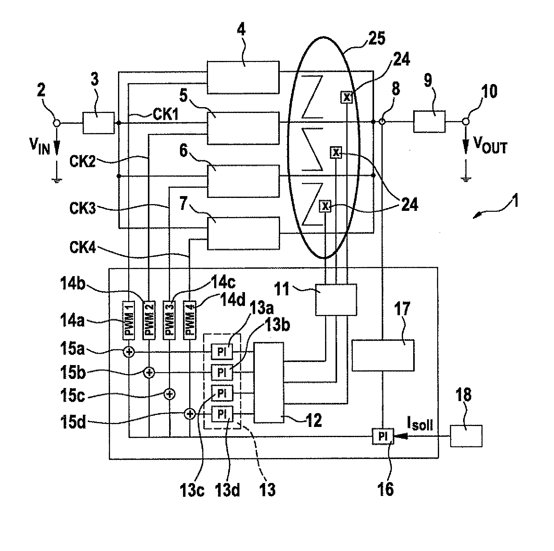
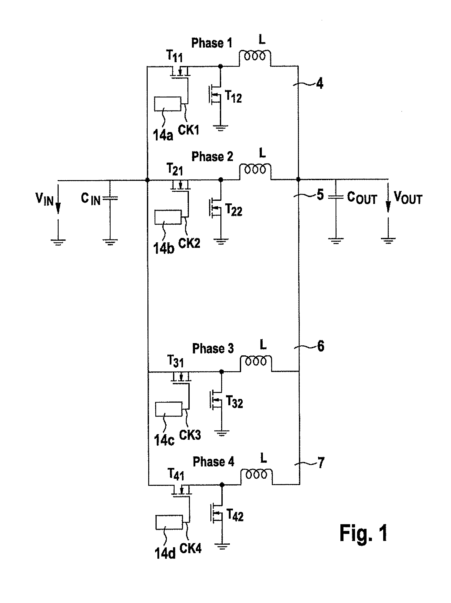
[0015]FIG. 1 shows a wiring diagram from which the basic design of the converter cells of a multiphase DC to DC voltage converter is apparent. This diagram shows that input voltage VIN is applied to the input terminal via a low pass filter, which has a capacitor CIN connected to ground, for example, to a parallel circuit of n converter cells, four converter cells in the shown exemplary embodiment. These converter cells are clocked with a time offset. A phase 1 is assigned to converter cell 4, a phase 2 is assigned to converter cell 5, a phase 3 is assigned to converter cell 6, and a phase 4 is assigned to converter cell 7.

[0016]Converter cell 4 has a transistor T11, which is connected to the input of the parallel circuit and connected to the output of a PWM generator 14a, a transistor T12, and a coil L. The first terminal of coil L is connected to the interconnection point between the two transistors T11 and T12. The other terminal of coil L is connected to the output of the paralle...


PUM


Abstract

A multiphase DC to DC voltage converter which has multiple converter cells which are situated parallel to one another and are clocked with a time offset. Furthermore, it contains one magnetic measuring bridge between the outputs of each two converter cells.

Description

FIELD OF THE INVENTION[0001]The present invention relates to a multiphase DC to DC voltage converter.BACKGROUND INFORMATION[0002]A method for generating control pulses for power semi-conductors, in particular for the purpose of generating offset control pulses for half-bridges which are coupled to multiphase converters or to DC to DC voltage converters, is described in German Patent Application No. DE 101 10 615 A1. In this method, the reference voltage is displaced by a delay time corresponding to the staggerings or a PWM signal is displaced by a delay time which corresponds to the period divided by the number of offsets.[0003]A device for supplying power to a multi-voltage on-board electrical system of a motor vehicle is described in German Patent Application No. DE 101 19 985 A1. This device has a multi-voltage on-board electrical system situated in a motor vehicle which provides at least one first and one second voltage level, each being different from the reference potential. T...

Claims


Application Information

Patent Timeline
Patent Type & Authority Applications(United States)
IPC IPC(8): G05F1/00
CPCH02M2001/0009H02M3/1584H02M1/0009
Inventor BLAUMEISER, BORISKRANZER, DIRKKONZILI, MARKUS
Owner ROBERT BOSCH GMBH
Why Eureka
Try Eureka