Thermally Conductive Silicone Grease Composition

Active Publication Date: 2011-02-17
DOW TORAY CO LTD
View PDF5 Cites 11 Cited by
  • Summary
  • Abstract
  • Description
  • Claims
  • Application Information

AI Technical Summary

Benefits of technology

[0014]The thermally conductive silicone grease composition of the inventi

Problems solved by technology

However, a problem associated with conventional silicone grease compositions is that a part of the oil bleeds out, and this impairs reliability of the respective electronic devices.
However, such a thermally conductive silicone grease composition was subject either to oil bleeding or to dripping from thick coating layers or from vertical surfaces under the effect of heat.

Method used


Image

  • Thermally Conductive Silicone Grease Composition
  • Thermally Conductive Silicone Grease Composition
  • Thermally Conductive Silicone Grease Composition

Examples


example 1

Practical Example 1

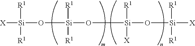
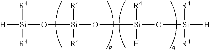
[0040]100 parts by mass of a dimethylpolysiloxane represented by the following general formula:

(wherein “m” is a value that occurs at viscosity of 2,000 mPa·s) and 2,360 parts by mass of a spherical aluminum oxide powder having an average particle diameter of 12 μm were premixed for 30 min. at room temperature and then mixed for another 60 min. under a reduced pressure and at a temperature of 150° C. Following this, the product was cooled to room temperature and mixed with 80 parts by mass of a copolymer of a methylhydrogensiloxane and a dimethylsiloxane having viscosity of 10 mPa·s and represented by the following formula:

whereby a thermally conductive silicone grease composition was obtained.

example 2

Practical Example 2

[0041]100 parts by mass of a dimethylpolysiloxane represented by the following general formula:

(wherein “m” is a value that occurs at viscosity of 10,000 mPa·s), 1,240 parts by mass of a spherical aluminum oxide powder having an average particle diameter of 12 μm, and 70 parts by mass an irregular-shaped zinc oxide powder having an average particle size of 0.1 μm were premixed for 30 min. at room temperature and then mixed for another 60 min. under a reduced pressure and at a temperature of 150° C. Following this, the product was cooled to room temperature and mixed with 14 parts by mass of a copolymer of a methylhydrogensiloxane and a dimethylsiloxane having viscosity of 10 mPa·s and represented by the following formula:

whereby a thermally conductive silicone grease composition was obtained.

example 3

Practical Example 3

[0042]100 parts by mass of a dimethylpolysiloxane represented by the following general formula:

(wherein “p” is a value that occurs at viscosity of 20 mPa·s), 2,560 parts by mass of a spherical aluminum oxide powder having an average particle diameter of 12 μm, 360 parts by mass of an irregular-shaped zinc oxide powder having an average particle size of 0.1 μm, and 7 parts by mass of a methyltrimethoxysilane were premixed for 30 min. at room temperature and then mixed for another 60 min. under a reduced pressure and at a temperature of 150° C. Following this, the product was cooled to room temperature and mixed with 2.7 parts by mass of a copolymer of a methylhydrogensiloxane and a dimethylsiloxane having viscosity of 10 mPa·s and represented by the following formula:

whereby a thermally conductive silicone grease composition was obtained.


PUM

PropertyMeasurementUnit
Temperatureaaaaaaaaaa
Lengthaaaaaaaaaa
Percent by massaaaaaaaaaa

Abstract

A thermally conductive silicone grease composition comprising at least the following components: an organopolysiloxane (A) represented by the following general formula: [wherein R1 designates identical or different univalent hydrocarbon groups; X designates identical or different univalent hydrocarbon groups or alkoxysilyl-containing groups of the following general formula: —R2—SiR1a(OR3)(3-a) (wherein R1 designates the previously mentioned groups; R2 designates oxygen atoms or alkylene groups; R3 designates alkyl groups; and ‘a’ is an integer ranging from 0 to 2); and ‘m’ and ‘n’ are integers equal to or greater than 0, respectively]; a thermally conductive filler (B); and an organopolysiloxane (C) having silicon-bonded hydrogen atoms on both molecular terminals and in the molecular chains; is characterized by excellent resistance to heat and reduced oil bleeding.

Description

TECHNICAL FIELD[0001]The present invention relates to a thermally conductive silicone grease composition which is characterized by excellent resistance to heat and reduced oil bleeding.BACKGROUND ART[0002]In recent years, following an increase in the degree of density and integration of hybrid ICs and printed circuit boards that carry transistors, ICs, memory elements, and other electronic components, various thermally conductive silicone grease compositions comprising an organopolysiloxane and a thermally conductive filler such as an aluminum oxide powder, zinc oxide powder or the like have been used in order to achieve efficient heat transfer from such devices (see Japanese Unexamined Patent Application Publications (hereinafter referred to as “Kokai”) Sho 50-105573, Sho 51-55870, and Sho 61-157587). However, a problem associated with conventional silicone grease compositions is that a part of the oil bleeds out, and this impairs reliability of the respective electronic devices.[0...

Claims


Application Information

Patent Timeline
IPC IPC(8): C10M107/50C10M125/10C10M125/04C10M125/26
CPCC08G77/12C08G77/18H01L2924/0002H01L2924/09701H01L23/3737C10N2220/084C10N2220/082C10N2220/022C10M2229/0515C08G77/20C08G77/60C08L83/04C08L83/14C09K5/14C10M169/02C10M2201/0416C10M2201/056C10M2201/0616C10M2201/0626C10M2201/1056C10M2201/145C10M2227/04C10M2227/065C10M2229/0415C10M2229/0425C10M2229/0435C10M2229/0445C10M2229/0465C08L83/00C08L2666/54H01L2924/00C10N2020/061C10N2020/06C10N2020/02
Inventor NAKAYOSHI, KAZUMIKATO, TOMOKO
Owner DOW TORAY CO LTD
Why Eureka
Try Eureka