Heat treatment method
a heat treatment and substrate technology, applied in the direction of sustainable manufacturing/processing, final product manufacturing, semiconductor/solid-state device details, etc., can solve the problems of warpage of the substrate, direct affecting the substrate warpage is more problematic, so as to improve the productivity of flat-panel displays or solar cells, prevent the deformation of the substrate caused during the heat treatment process, and improve the effect of the product quality
- Summary
- Abstract
- Description
- Claims
- Application Information
AI Technical Summary
Benefits of technology
Problems solved by technology
Method used
Image


Examples
first embodiment
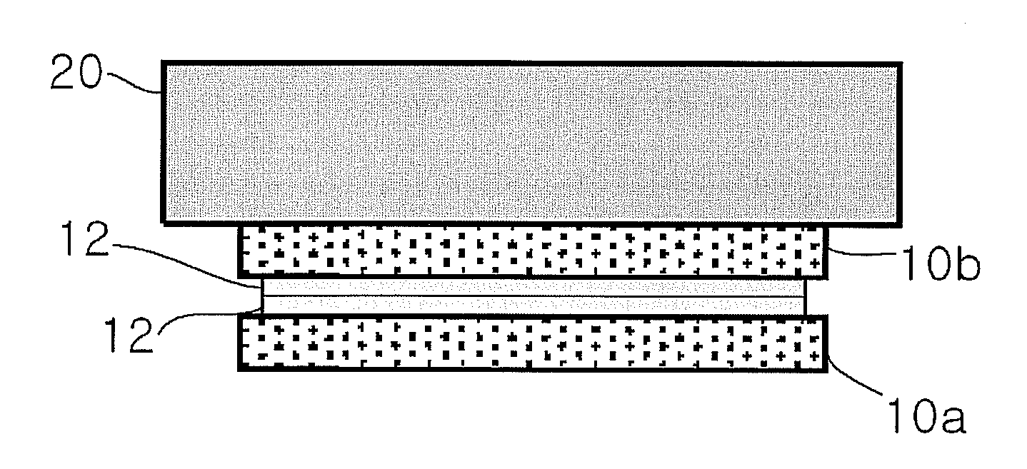
[0034]FIG. 2 is a view showing the configuration of a heat treatment method in accordance with the present invention. As shown therein, the heat treatment method in accordance with this embodiment is characterized in that a heat treatment process is performed under a condition where a first substrate 10a and a second substrate 10b are stacked, with thin films 12 respectively formed on the first substrate 10a and the second substrate 10b being in contact with each other, and a weight 20 having a predetermined mass is placed on top of the second substrate 10b.
[0035]In this embodiment, the weight 20 serves to apply a uniform load over the entire area of the first and second substrates 10a and 10b in order to suppress deformation of the first substrate 10a and the second substrate 10b, as shown in FIG. 3, due to differences in thermal expansion coefficient between the substrates 10a and 10b and the thin films 12. FIG. 3 is a view showing the problem aroused when a heat treatment proces...
second embodiment
[0037]FIG. 4 is a view showing the configuration of a heat treatment method in accordance with the present invention. As shown therein, the heat treatment method in accordance with this embodiment is characterized in that a heat treatment process is performed under a condition where a first group G1 is constituted by stacking a pair of a first substrate 10a and a second substrate 10b, with thin films 12 formed on the substrates 10a and 10b being in contact with each other, a second group G2 and a third group G3 each constituted by stacking a first substrate 10a and a second substrate 10b are sequentially stacked on the first group G1 in the same manner as the first group G1, and then a weight 20 having a predetermined mass is placed on top of the second substrate 10b of the third group G3. Herein, the number of groups to be stacked is not limited to three, it may be properly adjusted, exceeding three depending on the number of substrates required for one batch to be loaded on a heat...
third embodiment
[0043]FIG. 6 is a view showing the configuration of a heat treatment method in accordance with the present invention. As shown therein, the heat treatment method in accordance with this embodiment is characterized in that a heat treatment process is performed under a condition where a first to a third substrates 10a, 10b, and 10c are sequentially stacked such that a thin film 12 formed on the first substrate 10a is in contact with a bottom surface of the second substrate 10b stacked on top of the first substrate 10a, and a thin film 12 formed on the second substrate 10b is in contact with a bottom surface of the third substrate 10c stacked on top of the second substrate 10b, and then a weight 20 having a predetermined mass is placed on the third substrate 10c. Herein, the number of groups to be stacked is not limited to three, it may be properly adjusted, exceeding three depending on the number of substrates required for one batch to be loaded on a heat treatment apparatus.
[0044]FIG...
PUM
 Abstract
Description
Claims
Application Information
 - R&D
- Intellectual Property
- Life Sciences
- Materials
- Tech Scout
- Unparalleled Data Quality
- Higher Quality Content
- 60% Fewer Hallucinations
Browse by: Latest US Patents, China's latest patents, Technical Efficacy Thesaurus, Application Domain, Technology Topic, Popular Technical Reports.
© 2025 PatSnap. All rights reserved.Legal|Privacy policy|Modern Slavery Act Transparency Statement|Sitemap|About US| Contact US: help@patsnap.com