
Fluorescent lamp

a fluorescent lamp and fluorescent technology, applied in the field of fluorescent lamps, can solve the problems of low emission efficiency of blue-emitting phosphor, no clear means to optimize the action spectra of lighting sources currently, and no discussion on deterioration of visual environmen

Inactive Publication Date: 2011-02-17
PANASONIC CORP
View PDF0 Cites 14 Cited by
  • Summary
  • Abstract
  • Description
  • Claims
  • Application Information

AI Technical Summary

Benefits of technology

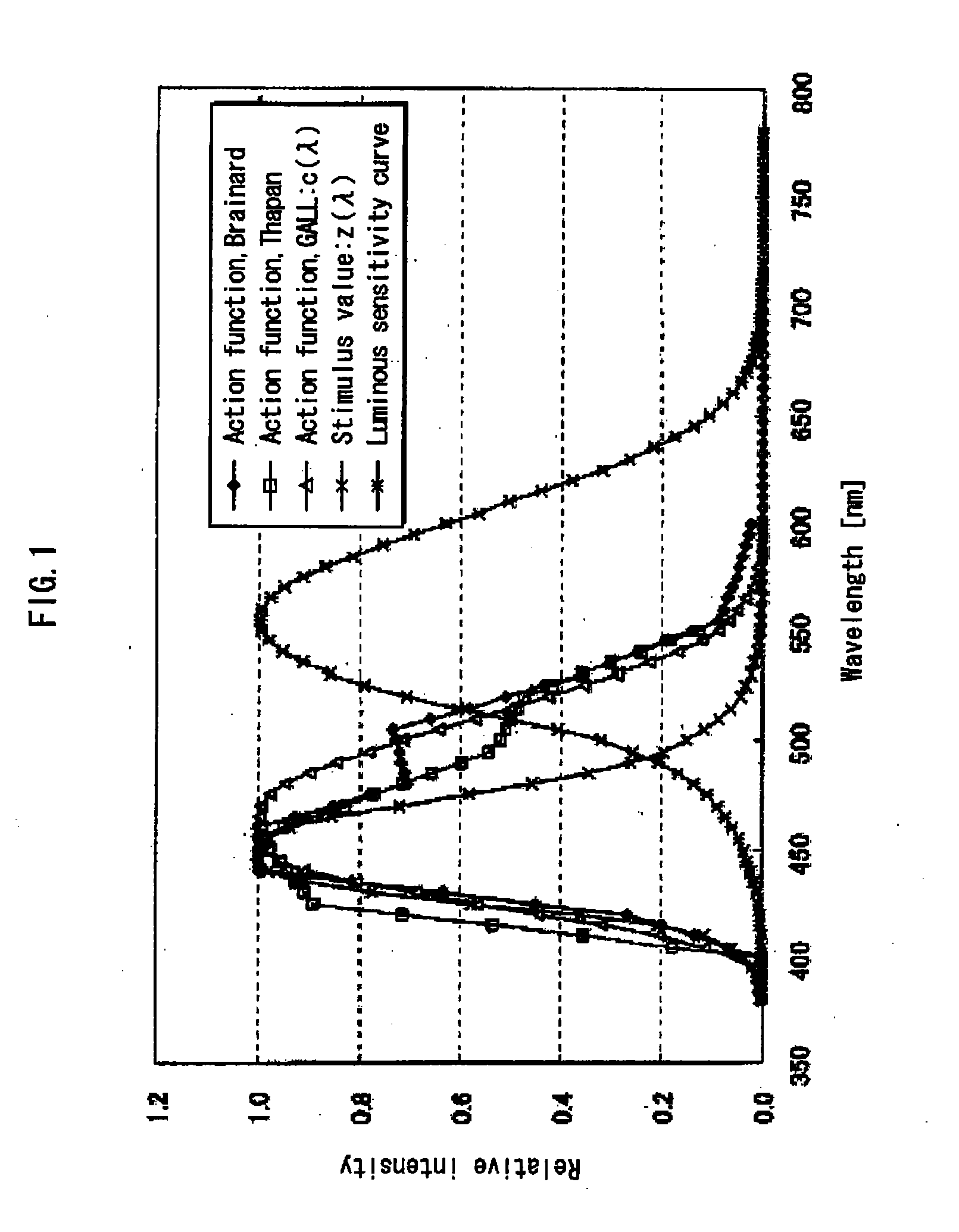
[0087]The present invention realizes an ultra-high color temperature fluorescent lamp with improved color rendering properties and a high efficiency by enhancing emission between blue emission and green emission of a fluorescent lamp which is constructed based on a narrow-band fluorescent lamp, the ultra-high color temperature fluorescent lamp achieving function effects of adjusting biological rhythms and promoting wakefulness of living bodies by suppressing melatonin secretion.
[0088]Enhancing at least emission between a main emission peak of a blue emitting rare-earth phosphor and a main emission peak of a green emitting rare-earth phosphor achieves higher melatonin suppression and at the same time improving the color rendering characteristics, that is, deterioration of appearance (chroma) of red and green, with respect to a narrow-band light source corresponding to a three-wavelength light source with the corresponding correlated color temperature.
[0089]This enables providing a fluorescent lamp and a lighting apparatus that achieve effects of adjusting biological rhythms and promoting wakefulness of living bodies by suppressing melatonin secretion in an efficient and natural visual environment while maintaining color rendering properties.
[0090]There are roughly two ways to enhance emission between the main emission peaks of the blue emitting rare-earth phosphor and the green emitting rare-earth phosphor.
[0091]The first way is to extend the half width from the emission peak of the blue emitting rare-earth phosphor (preferably 50 [nm] or more) toward a longer wavelength, whereby the above-mentioned effect can be achieved. The second way is to add a phosphor with an emission center whose main emission peak is located in a range between the emission peaks of the blue emitting rare-earth phosphor and the green emitting rare-earth phosphor (preferably from 480 [nm] to 520 [nm]).
[0092]It has been found out that especially by use of the latter way, preferably concentrating emission in the range of 480 [nm] to 520 [nm] when enhancing the emission between the main emission peaks between the blue emitting rare-earth phosphor and the green emitting rare-earth phosphor enables increasing Ra and Ri (especially R9) in a high Duv region, and it has been further found out that problems related to color rendition which these Ra, Ri and the like cannot express can be solved.

Problems solved by technology

However, concerning an action spectrum indicating suppression of melatonin secretion for adjusting biological rhythms and promoting wakefulness of living bodies, there are currently still various views, and no unique determination has been made.
However, in general, a blue-emitting phosphor is low in emission efficiency.
Yet, conventionally, a desirable emission spectrum by a narrow-band light source at an ultra-high color temperature, problems related to the color rendering thereof and the like have not been found out.
Accordingly, there exists no clear means to optimize the action spectra for lighting sources currently.
Furthermore, no discussion has been made on deterioration of a visual environment that occurs as a counteraction from a decrease in color rendering properties due to a higher color temperature in application to actual illumination.
Accordingly, problems arising from color rendering properties unique to the ultra-high color temperature, which cannot be expressed simply by values of the general color rendering index Ra and the color rendering indexes Ri, bases of the phenomenon, and measures for improvement have not been found.
However, there has been no attempt for such optimization.

Method used


Image

  • Fluorescent lamp
  • Fluorescent lamp
  • Fluorescent lamp

Examples


first embodiment

[0288]FIG. 10A schematically shows a fluorescent lamp 100 of an embodiment pertaining to the present invention. FIG. 10B schematically shows a longitudinal sectional view of a structure of the fluorescent lamp 100 of the present embodiment.

[0289]The fluorescent lamp 100 of the present embodiment includes a bulb 10 (lamp arc tube) composed of a glass tube and a phosphor layer 20 formed on an inner surface of the bulb 10. In the present embodiment, light emitted from the fluorescent lamp 100 has a high color temperature which is a correlated color temperature above 7100 [K]. In other words, the fluorescent lamp 100 of the present embodiment is a fluorescent lamp that has an ultra-high color temperature exceeding the highest light color 7100 [K] specified by JIS Z9112:1990 (or IEC 60081-1997) for fluorescent lamps for general lighting.

[0290]The phosphor layer 20 of the present embodiment includes a red emitting rare-earth phosphor, a green emitting rare-earth phosphor, and a blue emitt...

second embodiment

[0385]The following describes a second embodiment of the present invention. In the second embodiment, a theoretical explanation is given on a relative tendency of the effects caused by the present invention, based on the theoretical spectral distributions in a case where an emission center whose main emission peak is located between the main emission peaks of the blue emitting rare-earth phosphor and the green emitting rare-earth phosphor, preferably in a range of 480 [nm] to 520 [nm].

[0386]First, as a theoretical model of a conventional ordinary narrow-band fluorescent lamp, the following structure is theoretically simulated: the structure in which the phosphor layer includes at least a red emitting rare-earth phosphor containing a rare-earth element as an emission center whose emission peak is located in a range of 605 [nm] to 625 [nm], a green emitting rare-earth phosphor containing a rare-earth element as an emission center whose main emission peak is located in a range of 540 [...

third embodiment

[0402]The following describes a third embodiment of the present invention. In the third embodiment, a theoretical explanation is given on a relative tendency of advantageous effects achieved by the present invention, based on the theoretical spectral distributions in a case where the half width is extended toward a long wavelength from the emission peak of the blue emitting rare-earth phosphor.

[0403]FIGS. 36 to 38 show results of simulations performed under the same conditions as the second embodiment except the following, in order to simulate that a blue phosphor which was used to enhance the emission between the main emission peaks of the green emitting rare-earth phosphor and the blue emitting rare-earth phosphor and which has the main emission peak in a range of 440 [nm] to 460 [nm] is a blue emitting phosphor whose half width from the emission peak toward a longer wavelength is 50 [nm] or greater: the emission intensity of the blue emitting phosphor being 100% in the range of 4...


PUM


Abstract

Fluorescent lamp 100 has a light color with a correlated color temperature higher than 10000 [K] and lower than 17000 [K] and Duv in a range of −2.5 to 5, comprising arc tube 10 and phosphor layer 20 which includes at least: a red emitting rare-earth phosphor with a main emission peak (11) in 605-625 [nm]; a green emitting rare-earth phosphor with a main emission peak (12) in 540-550 [nm]; and a blue emitting rare-earth phosphor with a main emission peak (13) in 440-460 [nm], an action function efficiency of melatonin suppression for per unit luminous flux is higher than 1.0, and a general color rendering index Ra is 80 or higher. With the stated structure, the fluorescent lamp 100 suppresses melatonin secretion thereby achieving effects of adjusting biological rhythms and promoting wakefulness of living bodies, and also remedies the shortcomings in color rendering characteristics of the light source.

Description

TECHNICAL FIELD[0001]The present invention relates to a fluorescent lamp which provides photostimulation pertaining to secretion and suppression of melatonin of a living body.[0002]A fluorescent lamp of the present invention is a low-pressure lamp which has a phosphor applied therein, such as a compact fluorescent lamp, a hot cathode fluorescent lamp, a cold cathode fluorescent lamp, an electrodeless fluorescent lamp, and a dielectric barrier fluorescent lamp. A lighting apparatus of the present invention is a lighting apparatus including an irradiation apparatus in which the fluorescent lamp of the present invention is incorporated.BACKGROUND ART[0003]In recent years, melanopsin which contributes to regulation of photoperiodic biological rhythms was discovered in human bodies, and a study is conducted to develop a technology to realize lighting sources that are able to suppress melatonin secretion by photostimulating melanopsin, thereby adjusting the biological rhythms and promotin...

Claims


Application Information

Patent Timeline
IPC IPC(8): H01J1/62
CPCA61N5/0618A61N2005/0642H01J61/44A61N2005/0662A61N2005/0654
Inventor YAGI, HIROSHISHIMIZU, MASANORLHIGASHI, TORUKOBAYASHI, YUKI
Owner PANASONIC CORP
Learn More