
Semiconductor device having a fuse region and method for forming the same

Inactive Publication Date: 2011-02-03
SK HYNIX INC
View PDF13 Cites 2 Cited by
  • Summary
  • Abstract
  • Description
  • Claims
  • Application Information

AI Technical Summary

Benefits of technology

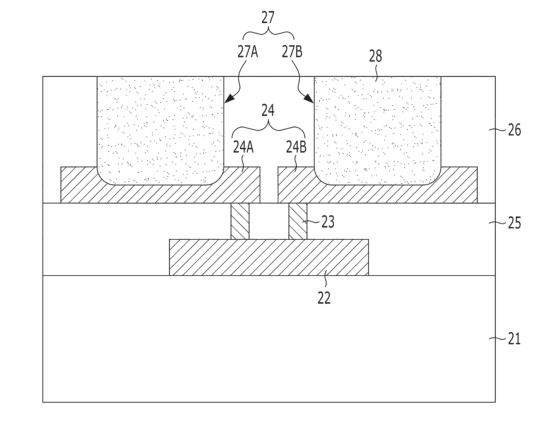
[0010]An embodiment of the present invention is directed to a fuse region for a semiconductor device that may reduce a probability of an occurrence of a crack at the edges of a bottom surface of a fuse box, and a method for forming the fuse region.

Problems solved by technology

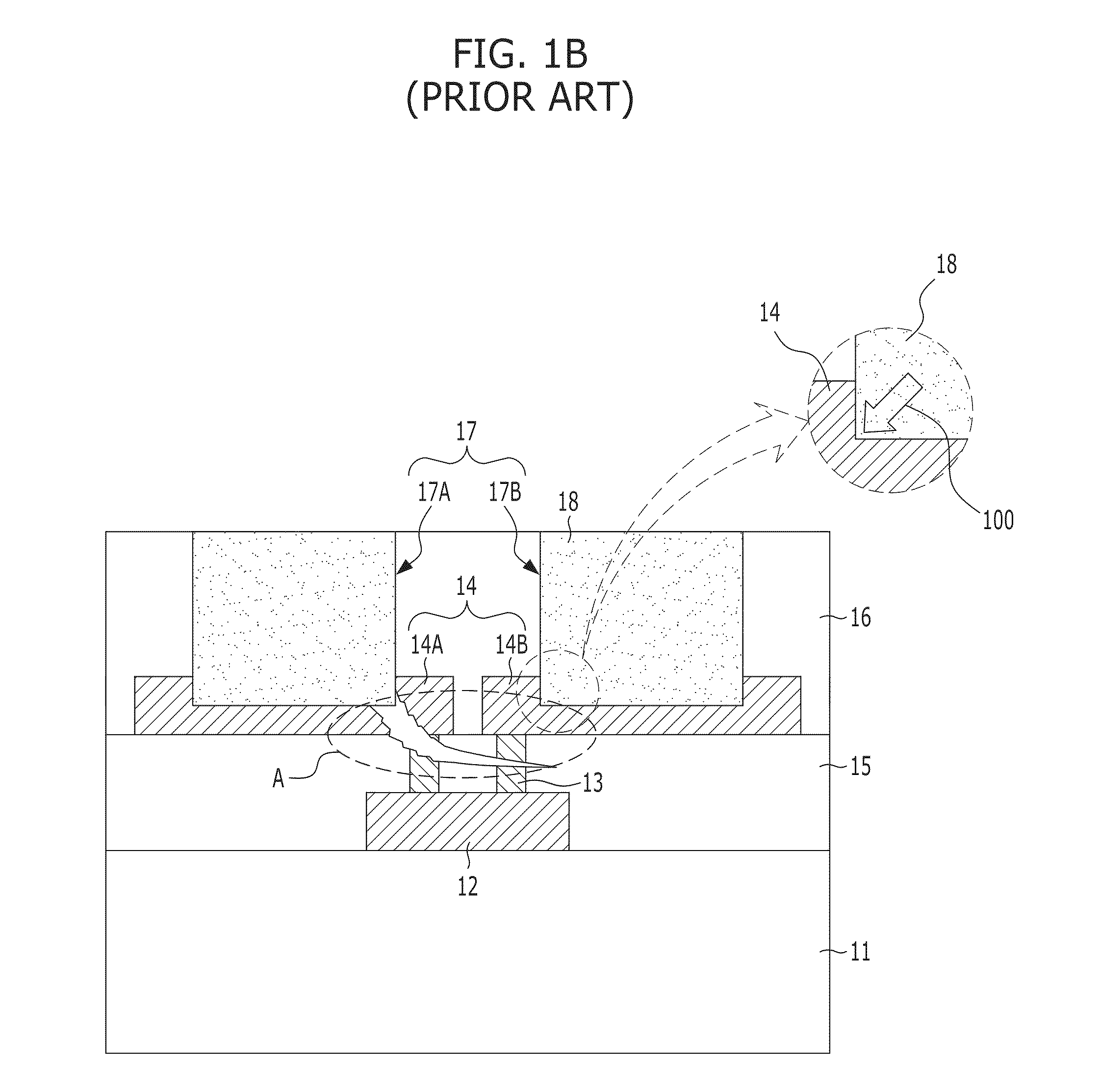
As a result, the repair yield and the reliability of a semiconductor device may be deteriorated.

Method used


Image

  • Semiconductor device having a fuse region and method for forming the same
  • Semiconductor device having a fuse region and method for forming the same
  • Semiconductor device having a fuse region and method for forming the same

Examples


Embodiment Construction

[0017]Exemplary embodiments of the present invention will be described below in more detail with reference to the accompanying drawings. The present invention may, however, be embodied in different forms and should not be construed as limited to the embodiments set forth herein. Rather, these embodiments are provided so that this disclosure will be thorough and complete, and will fully convey the scope of the present invention to those skilled in the art. Throughout the disclosure, like reference numerals refer to like parts throughout the various figures and embodiments of the present invention.

[0018]The drawings are not necessarily to scale and in some instances, proportions may have been exaggerated in order to clearly illustrate features of the embodiments. When a first layer is referred to as being “on” a second layer or “on” a substrate, it not only refers to a case where the first layer is formed directly on the second layer or the substrate but also a case where a third laye...


PUM


Abstract

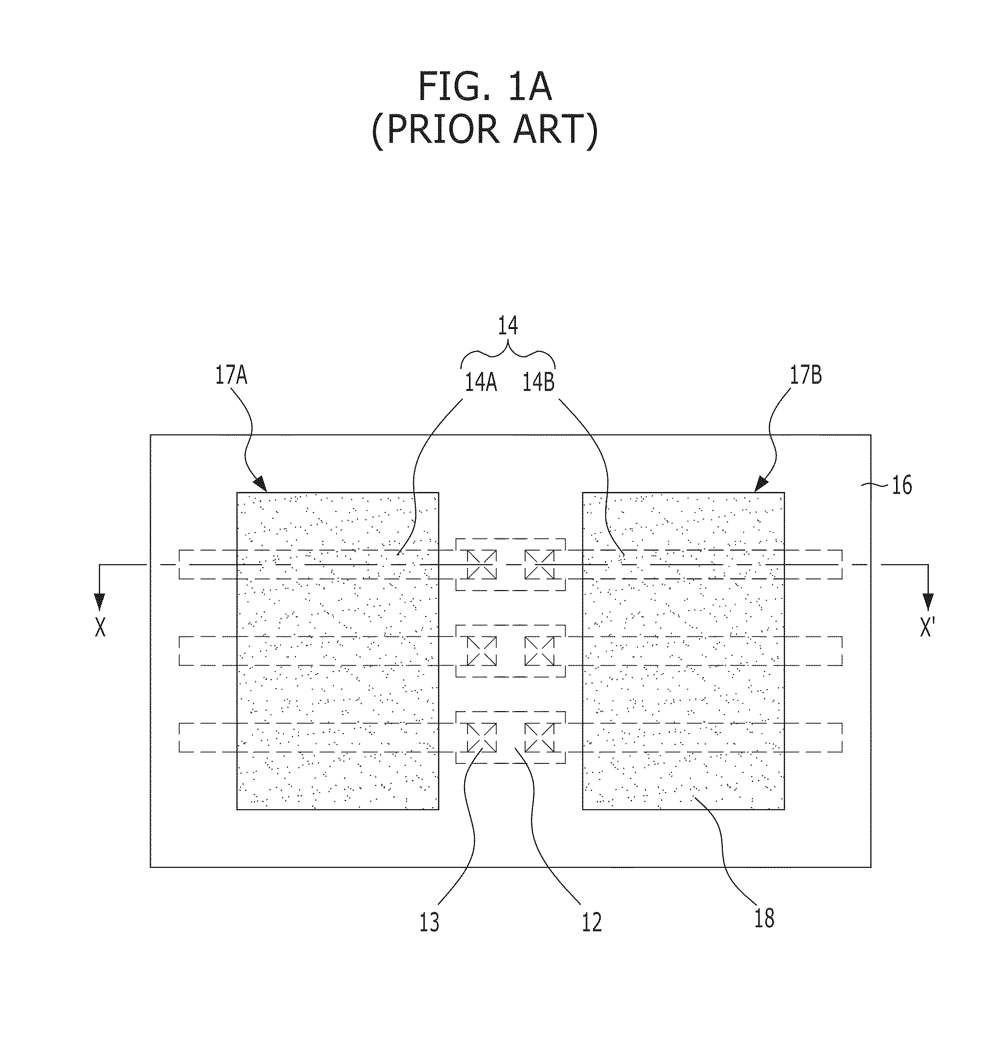
A semiconductor device having a fuse region, the fuse region includes a conductive pattern and a fuse box formed to partially expose the conductive pattern which have an inclined edge on a bottom surface.

Description

CROSS-REFERENCE TO RELATED APPLICATIONS[0001]The present application claims priority of Korean Patent Application No. 10-2009-0070658, filed on Jul. 31, 2009, which is incorporated herein by reference in its entirety.BACKGROUND OF THE INVENTION[0002]Exemplary embodiments of the present invention relate to a technology for fabricating a semiconductor device, and more particularly, to a fuse region and technology for fabricating the fuse region, for example, to a fuse region including a dual fuse of a semiconductor device.[0003]In general, redundancy cells for replacing defective cells are formed in the semiconductor memory device for improving the production yield, and the replacement process is referred to as a repair process.[0004]A semiconductor device includes a fuse region for the above-described repair process. Typically, a fuse region includes a fuse and a fuse box which is formed in a protective layer covering the fuse and exposes a portion of the fuse. The fuse may be formed...

Claims


Application Information

Patent Timeline
IPC IPC(8): H01L23/525H01L21/768
CPCH01L23/5256H01L23/5258H01L2924/0002H01L2924/00H01L21/82H01L23/62
Inventor LEE, KYUNG-JIN
Owner SK HYNIX INC
Learn More