
Bending transducer for generating electrical energy from mechanical deformations

a transducer and mechanical deformation technology, applied in the direction of generators/motors, transportation and packaging, tyre parts, etc., can solve the problems of limited reliability, large surface area and thus expensive piezoelectric elements are generally required, and the piezoelectric element at the housing connection is exposed to only relatively minor changes in mechanical stress, so as to achieve simple and reliable contact

Active Publication Date: 2011-02-03
ROBERT BOSCH GMBH
View PDF13 Cites 12 Cited by
  • Summary
  • Abstract
  • Description
  • Claims
  • Application Information

AI Technical Summary

Benefits of technology

[0009]The bending transducer according to the present invention permits simple and reliable contacting of the piezoelectric element with the support element, in particular even with structure sizes in the area of precision mechanics. The bending transducer is also suitable for applications in sensor systems and actuator systems, in particular also for generating energy, it also being usable as an energy source for separate or even autarkic systems, e.g., sensor modules.
[0011]According to the present invention, it is possible to mechanically attach piezoelectric elements to the structure of the connecting electrodes. An additional wire or spring contacting may therefore be eliminated. Advantages include simpler manufacturing and assembly as well as increased reliability, in particular due to the improved stability.
[0015]This also makes it possible to use metal supports in particular. Metal supports made of steel plate or brass plate, for example, have a high deflectability, which allows a high piezoelectric voltage of the applied piezoelectric element. In addition, they have a good elasticity with low energy absorption and little material fatigue, so the support is able to remain stable over the lifetime of the bending element.
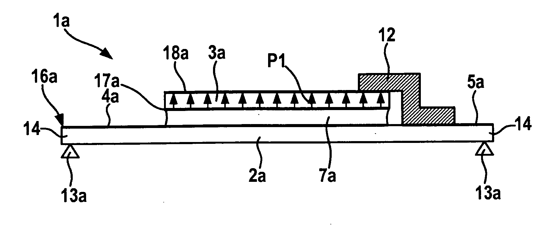
[0018]In the embodiment of the piezoelectric element having only one segment of uniform polarity, such a compact layer structure may be achieved, on the one hand, by directly contacting the first electrode formed on the connecting side of the piezoelectric element via a conductive connecting area and, on the other hand, the second electrode is not only formed on the top side of the piezoelectric element opposite the connecting side but also extends at least over a lateral edge area and advantageously also to the connecting side, forming a (relatively small) contacting area there which is contacted with the second connecting electrode of the support device via a second conductive connecting middle area.
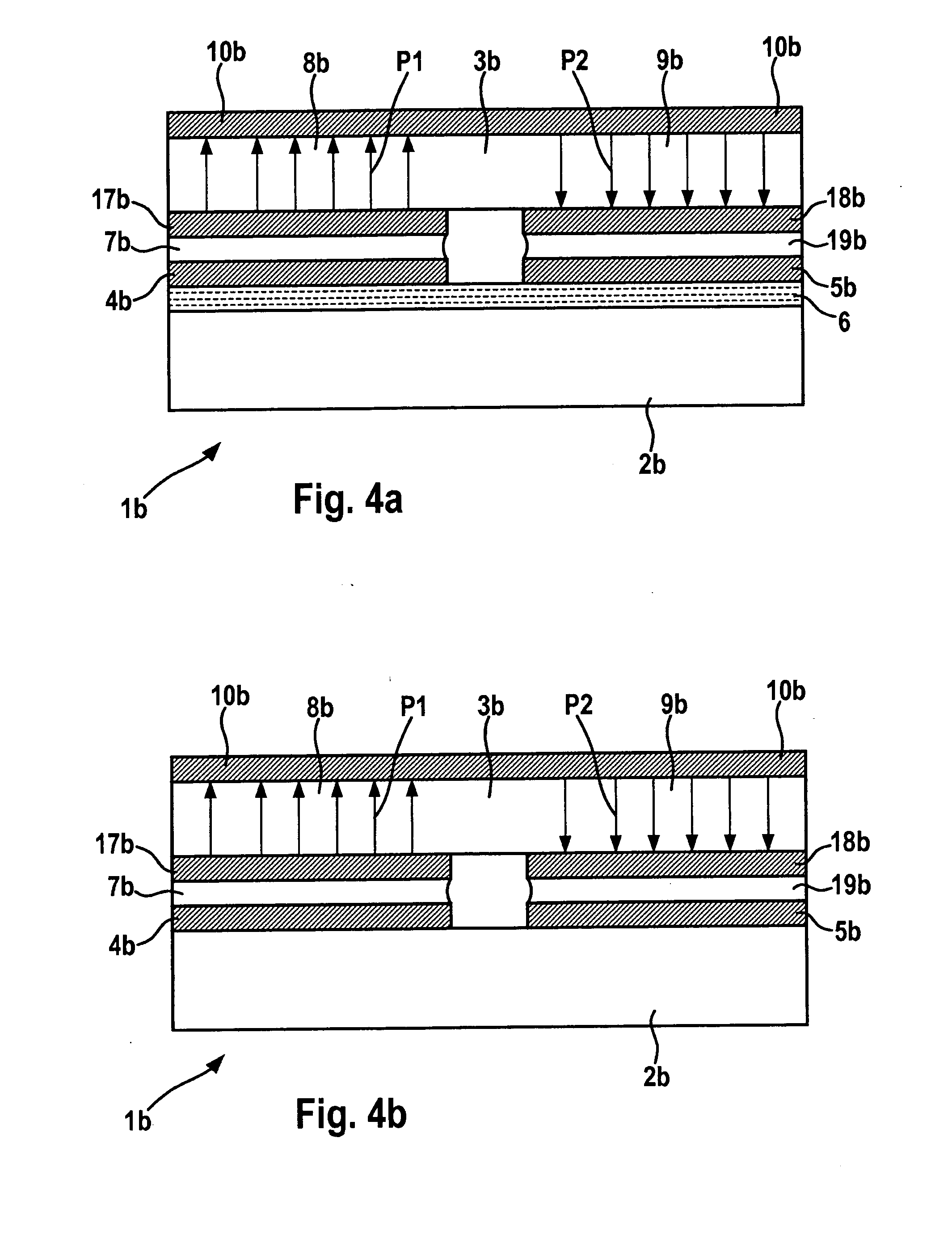
[0020]The bending transducer may thus be designed completely as a stack of layers including the support device, the piezoelectric element, the conductive adhesive or solder areas and the electrodes or connecting electrodes, in particular having plane-parallel layers in the undeformed state and thus having a compact and mechanically stable structure.
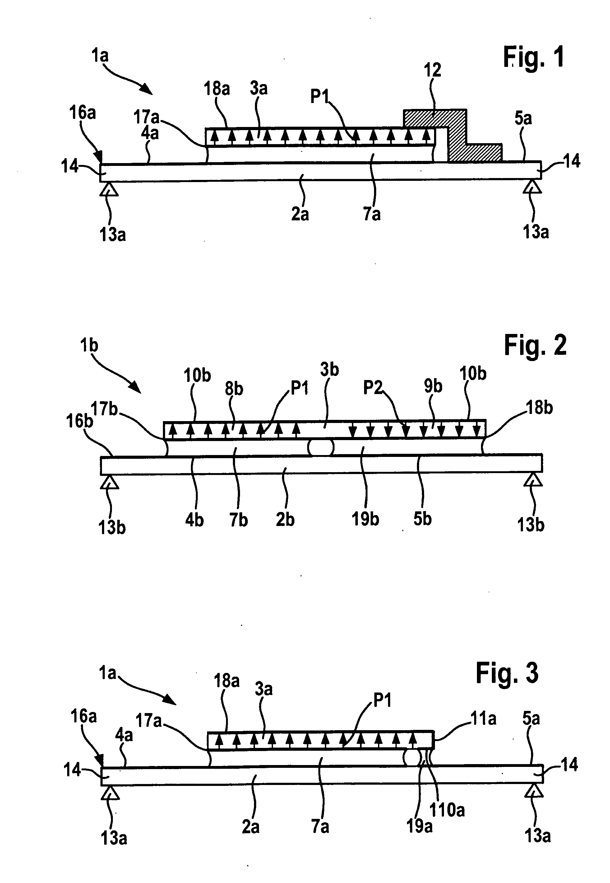
[0021]The piezoelectric element may be designed in one-piece in particular, having multiple segments if necessary. In addition, multiple piezoelectric elements may also be provided on a shared support device, e.g., in series connection to increase the achievable voltage or in parallel connection to increase the amperage. The piezoelectric elements here may absorb bending stresses, for example, in different areas of the support device and for different bending directions. Furthermore, a piezoelectric element having more than two electrodes may be provided, e.g., with four electrodes situated in a cross pattern to be able to generate energy with different bending stresses.

Problems solved by technology

The use of a sufficiently large-surface and thus expensive piezoelectric element is generally required for such configurations, the areas of the piezoelectric element at the housing connection being exposed to only relatively minor changes in mechanical stress.
However, these wire connections are also exposed to the mechanical stresses that occur and have, with respect to the repeated deformations, only limited reliability.

Method used


Image

  • Bending transducer for generating electrical energy from mechanical deformations
  • Bending transducer for generating electrical energy from mechanical deformations
  • Bending transducer for generating electrical energy from mechanical deformations

Examples


Embodiment Construction

[0029]A bending transducer 1a shown in FIG. 1 includes a deformable support 2a and a piezoelectric element 3a. Support 2a has a flat and plane-parallel shape and is elastically deformable. It is supported or clamped here with its two opposite side areas 14 on supporting elements 13a, thus allowing deformation to occur between these supporting elements, in particular a bending deformation. A first connecting electrode 4a and second connecting electrode 5a are applied to top side 16a of support 2a as part of a structured conductive layer, in particular a metal layer, with the aid of a lithographic and etching process, and extend laterally outward.

[0030]Piezoelectric element 3a is also designed to be flat. It is manufactured from a ceramic material in particular and in this specific embodiment has a uniform direction of polarization P1. On its bottom side, functioning as the connecting side, it has a first lower electrode 17a, and on its top side it has a second upper electrode 18a, bo...


PUM


Abstract

A bending transducer for generating electrical energy from deformations includes at least: one deformable support device, on which a first connecting electrode and a second connecting electrode are formed, one piezoelectric element attached to the support device having a least one first electrode and one second electrode, the first connecting electrode being contacted with the first electrode of the piezoelectric element, and the second connecting electrode being contacted with the second electrode of the piezoelectric element. The first connecting electrode and / or the second connecting electrode are applied as a structured conductive layer to the support device in at least some areas.

Description

BACKGROUND OF THE INVENTION[0001]1. Field of the Invention[0002]The present invention relates to a bending transducer for generating electrical energy from mechanical deformations.[0003]2. Description of Related Art[0004]Piezoelectric transducer mechanisms are used in the area of sensor and actuator systems in particular. For converting the mechanical stresses occurring in deformed structures, a piezoelectric element is generally coupled directly to a support element, i.e., a support structure, whereby the support structure may also be a second piezoelectric element (known as a piezoelectric bimorph). The piezoelectric element here has two electrodes for supplying and removing electrical charges to and from an electronic interface. The electrodes here are generally designed to be on the opposite sides of the piezoelectric element, which is usually flat.[0005]For example, published German patent application document DE 10 2005 062 872 A1 describes a device for detecting the rolling m...

Claims


Application Information

Patent Timeline
IPC IPC(8): B60C23/04H02N2/18
CPCB60C23/0411H01L41/1134H01L41/047H10N30/875H10N30/304
Inventor HORTIG, MICHAELPANNEK, THORSTENKLETT, GUSTAVKECK, MARIAN
Owner ROBERT BOSCH GMBH
Learn More