
Metallic material for a connecting part and a method of producing the same

a technology of connecting parts and metal materials, which is applied in the direction of conductive materials, surface reaction electrolytic coatings, coupling device connections, etc., can solve the problems of inferior conduction between the terminals, the difficulty of plugging in/out such a connector, and the inability to achieve the effect of sufficient gloss

Inactive Publication Date: 2011-01-27
FURUKAWA ELECTRIC CO LTD
View PDF10 Cites 9 Cited by
  • Summary
  • Abstract
  • Description
  • Claims
  • Application Information

AI Technical Summary

Benefits of technology

[0032]The metallic material for a connecting part of the present invention, which has, at the outermost surface of a rectangular wire material (including a rectangular rod material) of copper and a copper alloy as a base material, a layer substantially composed of copper and tin and containing at least one selected from the group consisting of zinc, indium, antimony, gallium, lead, bismuth, cadmium, magnesium, silver, gold, and aluminum, in a total amount of 0.01% or more and 1% or less in terms of mass ratio with respect to the content of tin, can serve as a metallic material that is independent of surface unevenness of the base material surface, has sufficient gloss after a heat treatment, and has very high preliminary solderability and post-plating property for the promotion of wetting by solder.
[0033]The metallic material for a connecting part of the present invention, which has, at the outermost surface of a rectangular wire material (including a rectangular rod material) of copper or a copper alloy as a base material, a layer containing tin as a main component and further containing an element selected from at least one group among the following two groups of (A) and (B) in a total amount of 0.01% by mass or more and 2% by mass or less, can serve as a metallic material that is independent of surface unevenness of the base material surface, has sufficient gloss after a heat treatment, and does not easily have the occurrence of whiskers;
[0034](A) at least one element selected from the group consisting of gallium, indium, lead, bismuth, cadmium, magnesium, zinc, sliver, and gold is contained, in an amount of 0.01% by mass or more and 1% by mass or less for individual element;
[0035](B) at least one element selected from the group consisting of aluminum and copper is contained, in an amount of 0.01 to 0.5% by mass for individual element.
[0036]Other and further features and advantages of the invention will appear more fully from the following description, appropriately referring to the accompanying drawings.

Problems solved by technology

In particular, plugging-in / out such a connector is difficult in a narrow space such as the engine room of a vehicle, and it has been strongly demanded to reduce the force for plugging in / out such a connector.
However, because the Sn plating layer is soft, a fretting phenomenon may occur between contact faces of the terminals, thereby causing inferior conduction between the terminals.
When this phenomenon occurs between the terminals, conduction between the terminals results in inferior.

Method used


Image

  • Metallic material for a connecting part and a method of producing the same
  • Metallic material for a connecting part and a method of producing the same
  • Metallic material for a connecting part and a method of producing the same

Examples


example 1

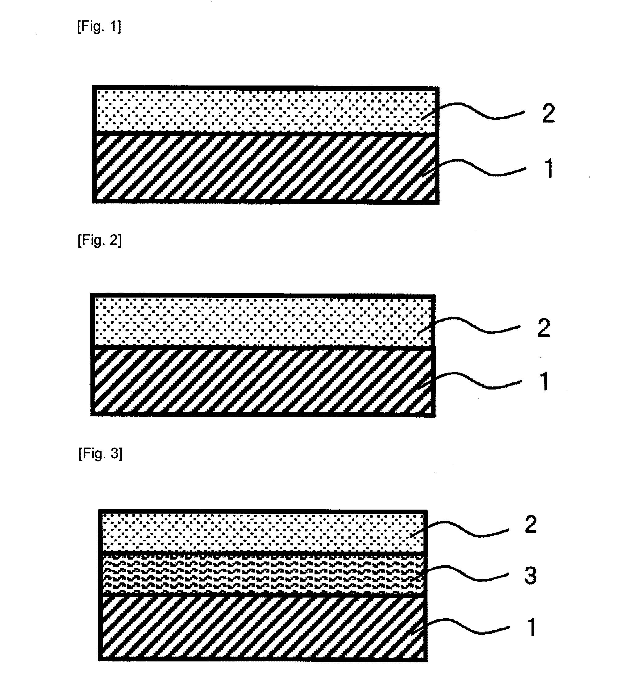
[0083]A rectangular wire of Corson alloy having a width of 0.64 mm was subjected to tin alloy plating to a thickness of 0.5 μm. Thereafter, the material was subjected to a reflow treatment at 350° C. for 10 seconds, and thus a rectangular wire material as shown in the partially enlarged schematic cross-sectional view of FIG. 1 was obtained. In FIG. 1, a part near the center point of one side of the rectangular wire material is shown in an enlarged view (the same in the following figures). In FIG. 1, the reference numeral 1 denotes a base material, and the reference numeral 2 denotes a copper-tin alloy layer.

example 2

[0085]A rectangular wire of Corson alloy having a width of 0.64 mm was subjected to copper plating to a thickness of 0.3 μm, and then was subjected to tin alloy plating to a thickness of 0.5 μm. Thereafter, the material was subjected to a reflow treatment at 500° C. for 5 seconds, and thus a rectangular wire material as shown in the partially enlarged schematic cross-sectional view of FIG. 2 was obtained. In FIG. 2, the reference numeral 1 denotes a base material, and the reference numeral 2 denotes a copper-tin alloy layer. The copper plating layer had completely reacted with the tin alloy plating of the outermost layer, by the reflow treatment, and converted to a copper-tin alloy layer 2.

example 3

[0087]A rectangular wire of Corson alloy having a width of 0.64 mm was subjected to nickel plating to a thickness of 0.4 μm, subsequently subjected to copper plating to a thickness of 0.3 μm, and then subjected to tin alloy plating to a thickness of 0.5 μm. Thereafter, the material was subjected to a reflow treatment at 500° C. for 5 seconds, and thus a rectangular wire material as shown in the partially enlarged schematic cross-sectional view of FIG. 3 was obtained. In FIG. 3, the reference numeral 1 denotes a base material, the reference numeral 2 denotes a copper-tin alloy layer, and the reference numeral 3 denotes a nickel layer. The copper plating layer had completely reacted with the tin alloy plating of the outermost layer, by the reflow treatment, and converted to a copper-tin alloy layer 2.


PUM

PropertyMeasurementUnit
Percent by massaaaaaaaaaa

Abstract

A metallic material for a connecting part, having a rectangular wire material of copper or a copper alloy as a base material, and formed at an outermost surface thereof, a copper-tin alloy layer substantially composed of copper and tin, wherein the copper-tin alloy layer of the outermost surface further contains at least one selected from the group consisting of zinc, indium, antimony, gallium, lead, bismuth, cadmium, magnesium, silver, gold, and aluminum, in a total amount of 0.01% or more and 1% or less in terms of mass ratio with respect to the content of the tin.

Description

TECHNICAL FIELD[0001]The present invention relates to a metallic material for a connecting part and a method for producing the same, and more particularly, the present invention relates to a metallic material for a connecting part having sufficient gloss after a reflow, and a method for producing the same.BACKGROUND ART[0002]A plated material produced by providing a plating layer of, for example, tin (Sn) or a tin alloy, on an electroconductive base material, such as copper (Cu) or a copper alloy (hereinafter, appropriately referred to as base material), is known as a high performance conductor material having the excellent electroconductivity and mechanical strength of the base material, as well as the excellent electrical connectivity, corrosion resistance, and solderability of the plating layer. Thus, such plated materials are widely used in various terminals, connectors, and the like.[0003]In recent years, since a fitting-type connector is multipolarized with advancement of elec...

Claims


Application Information

Patent Timeline
IPC IPC(8): B23K35/02C22F1/00
CPCC25D5/12C25D5/50C25D7/0607H01B1/026H01R13/03Y10T428/1291Y10T428/12222Y10T428/12917Y10T428/12715Y10T428/12438Y10T428/12722Y10S428/929
Inventor MITOSE, KENGOKITAGAWA, SHUICHIOGIWARA, YOSHIAKI
Owner FURUKAWA ELECTRIC CO LTD
Learn More