
LED lighting apparatus to dissipate heat by fanless ventilation

Inactive Publication Date: 2011-01-27
YOO +1
View PDF10 Cites 46 Cited by
  • Summary
  • Abstract
  • Description
  • Claims
  • Application Information

AI Technical Summary

Benefits of technology

[0021]As described above, according to the present invention, because the LED lighting apparatus dissipating heat by fanless ventilation includes a heat radiation housing that has a heat radiation frame provided around the body of the heat radiation housing and spaced apart from the body and also has linear heat radiation fins configured to minimize interference to air flow and to maximize the heat radiation area, the LED lighting apparatus has a significantly expanded heat radiation area and thus can dissipate heat much more effectively through ventilation by natural convection without a blowing fan, and consequently, and this extends the life span of the LED lighting apparatus and improves its quality.

Problems solved by technology

However, a LED lighting apparatus generates a great amount of heat.
As these features hinder ventilation, the surface area of the heat radiation fins 133 cannot serve as an effective heat exchange area.
In the above structure, if the interval between the heat radiation fins 133 is widened for the purpose of ventilation, the heat radiation area becomes insufficient, and as a result the heat dissipation performance goes down.
In this case, the fan may increase the cost of manufacturing and generate noises.
In addition, because the life span of the blowing fan is far shorter than that of LEDs, it may diminish the advantage of the LED lighting apparatus in its long life span.

Method used


Image

  • LED lighting apparatus to dissipate heat by fanless ventilation
  • LED lighting apparatus to dissipate heat by fanless ventilation
  • LED lighting apparatus to dissipate heat by fanless ventilation

Examples


Embodiment Construction

[0032]Hereinafter, the LED lighting apparatus dissipating heat by fanless ventilation according to one embodiment of the present invention will be described in more detail with reference to the accompanying drawings.

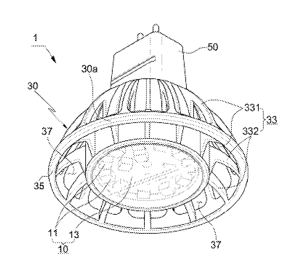
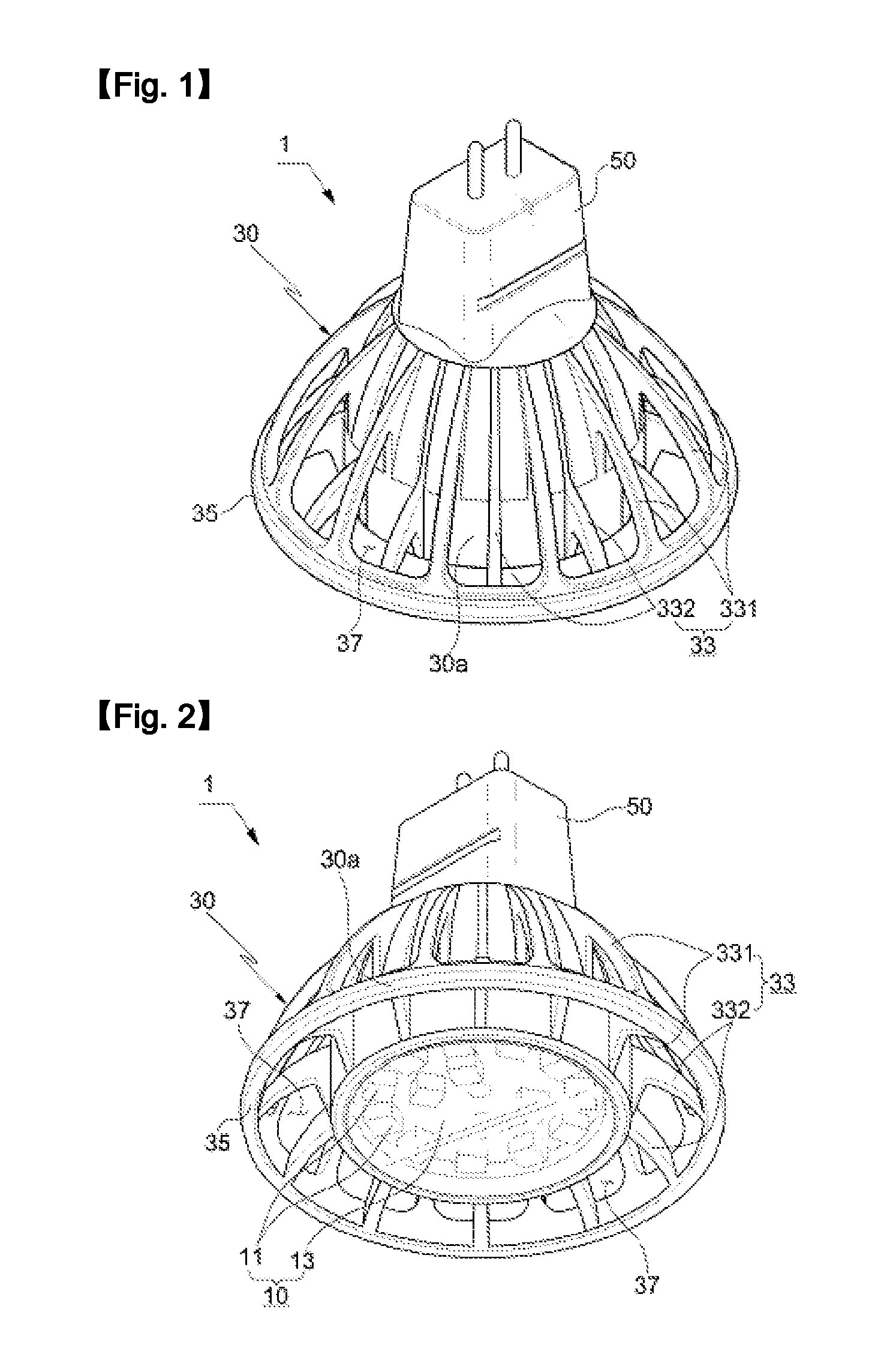
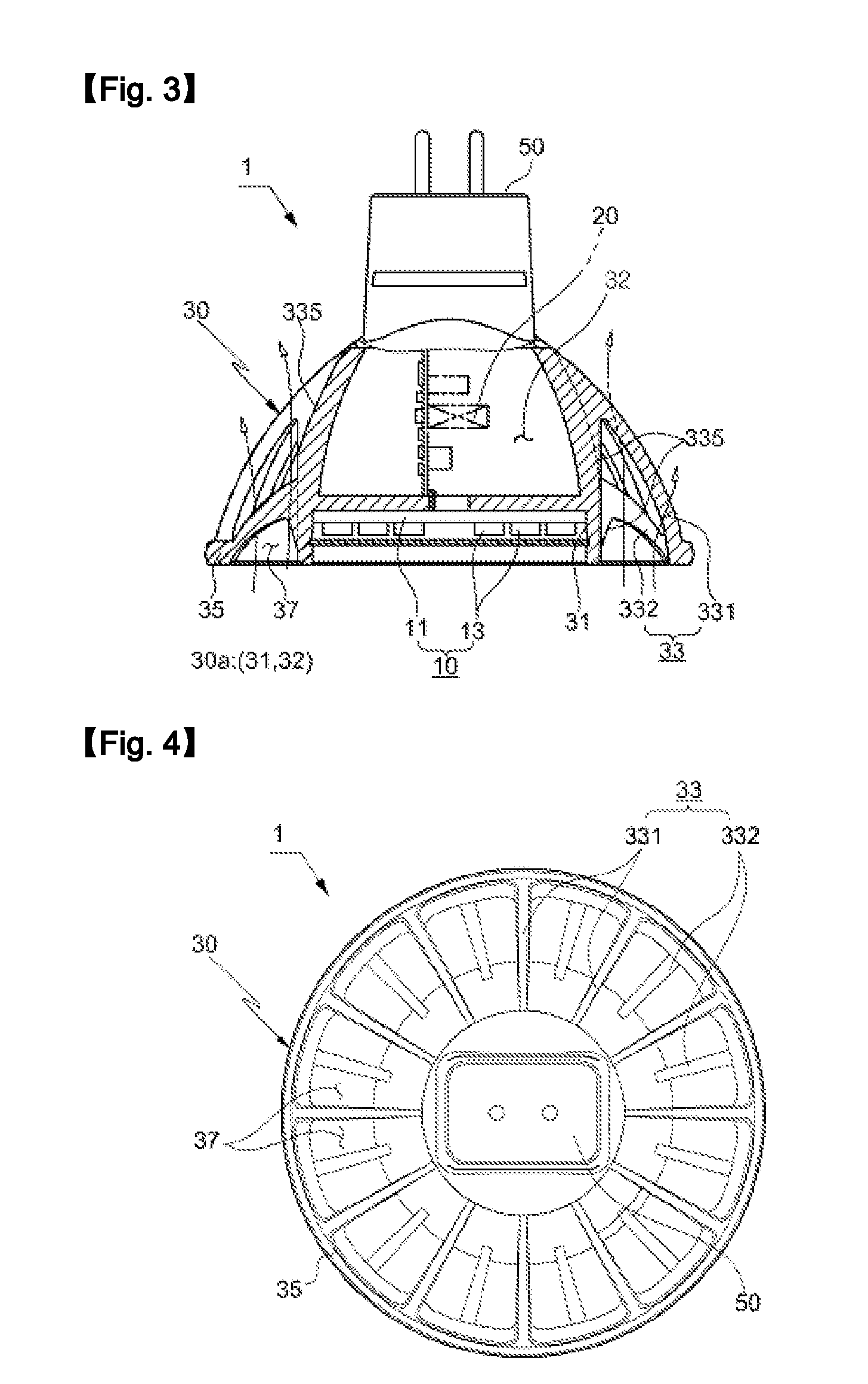
[0033]FIG. 1 is a perspective view showing the structure of the LED lighting apparatus 1 according to one embodiment of the present invention, and FIG. 2 is a bottom perspective view of FIG. 1, FIG. 3 is a longitudinal sectional view of FIG. 1, FIG. 4 is a plan view of FIG. 1, and FIG. 5 is a bottom view of FIG. 1.

[0034]As shown in FIGS. 1 to 5, the LED lighting apparatus 1 includes a light source part 10 including at least one LED 11 and a PCB 13 used to mount the LED and a heat radiation housing 30 provided at the upper portion thereof with a terminal part 50, in which the heat radiation housing 30 receives and supports the light source part 10 and performs the function of heat dissipation. The heat radiation housing 30 includes a body 30a in which a light source insta...


PUM


Abstract

An LED lighting apparatus dissipating heat by fanless ventilation including a heat radiation housing that has a heat radiation frame provided around the body of the heat radiation housing and spaced apart from the body and also has linear heat radiation fins configured to minimize interference to air flow and to maximize the heat radiation area, thereby expanding the heat radiation area significantly and thus dissipating heat much more effectively through ventilation by natural convection without a blowing fan, and consequently, extending the life span of the LED lighting apparatus and improving its quality. The LED lighting apparatus comprises a light source part including at least one LED and a PCB used to mount the LED; and a heat radiation housing provided at the upper portion thereof with a terminal part, receiving and supporting the light source part and dissipating heat.

Description

TECHNICAL FIELD [0001]The present invention relates to an LED lighting apparatus that dissipates heat by fanless ventilation, comprising a heat radiation housing that has a heat radiation frame provided around the body of the heat radiation housing and spaced apart from the body and also has linear heat radiation fins configured to minimize interference to air flow and to maximize the heat radiation area, thereby expanding the heat radiation area significantly and thus dissipating heat much more effectively through ventilation by natural convection without a blowing fan, and consequently, extending the life span of the LED lighting apparatus and improving its quality.BACKGROUND ART [0002]A light emitting diode (LED) has a smaller size and a longer life span compared with conventional light sources. In addition, because a LED converts electrical energy directly to optical energy, it reduces power consumption and therefore can emit high-intensity light with superior energy efficiency....

Claims


Application Information

Patent Timeline
IPC IPC(8): H01J61/52
CPCF21Y2101/02F21K9/137F21V29/83F21V29/773F21V29/75F21K9/233F21Y2115/10
Inventor YOO, YOUNG HO
Owner YOO
Learn More