
Suspended media membrane biological reactor system and process including suspension system and multiple biological reactor zones

a biological reactor and suspension membrane technology, applied in the field of wastewater treatment systems and methods, can solve the problems of hazards for all life forms caused by wastag

Inactive Publication Date: 2011-01-27
SIEMENS ENERGY INC +1
View PDF71 Cites 26 Cited by
  • Summary
  • Abstract
  • Description
  • Claims
  • Application Information

AI Technical Summary

Benefits of technology

[0068]The systems and methods of the present invention overcome the deleterious effects of using powdered activated carbon, while providing the same and additional advantages.

Problems solved by technology

The problems associated with simply discharging wastewater in water sources such as rivers, lakes and oceans, the standard practice up until about a half century ago, are apparent—the biological and chemical wastes create hazards to all life forms including the spread of infectious diseases and exposure to carcinogenic chemicals.

Method used


Image

  • Suspended media membrane biological reactor system and process including suspension system and multiple biological reactor zones
  • Suspended media membrane biological reactor system and process including suspension system and multiple biological reactor zones
  • Suspended media membrane biological reactor system and process including suspension system and multiple biological reactor zones

Examples


example 1

[0192]A pilot scale programmable logic controlled membrane biological reactor system (Petro™ MBR Pilot Unit available from Siemens Water Technologies, Rothschild, Wis., USA) having an aeration tank with an anoxic section, with an capacity of approximately 3,785 liters (1) (1,000 gallons (gal)) and a membrane operating system equivalent to a commercial membrane biological reactor system, was modified to accommodate the granular activated carbon addition described in the present invention. A wedge wire screen was situated at the inlet of a pump that transferred mixed liquor from the aeration tank to the membrane operating system.

[0193]A base synthetic feedstock included water having the following concentrations of organic / inorganic matter: 48 grams per liter (g / l) (48 ounces per cubic foot (oz / cf)) of sodium acetate; 16 g / l (16 oz / cf) of ethylene glycol; 29 g / l (29 oz / cf) of methanol; 1.9 g / l (1.0 oz / cf) of ammonium hydroxide; and 0.89 g / l (0.89 oz / cf) of phosphoric acid. The ammonium...

example 2

[0199]Laboratory particle suspension scale tests were performed using a 2000 milliliter graduated cylinder having a rotameter connected to a source of compressed air and a tube from the outlet of the rotameter to a tube that reached to the bottom of the graduated cylinder. 20 g (0.7 oz) of thoroughly dried granular activated carbon were placed in the cylinder. Room temperature distilled water was also added to the cylinder wetting the particles. The contents of the cylinder were mixed with a spatula to suspend the entire contents and remove air bubbles.

[0200]Air was added to the tube in the cylinder at increasing rates until the first solids were suspended and the air flow was recorded. The airflow was increased until approximately 50% of the solids were suspended (based upon the amount of carbon remaining on the bottom of the cylinder) and the airflow was recorded. Airflow was again increased until all of the granular activated carbon was suspended. The final airflow was recorded. ...

example 3

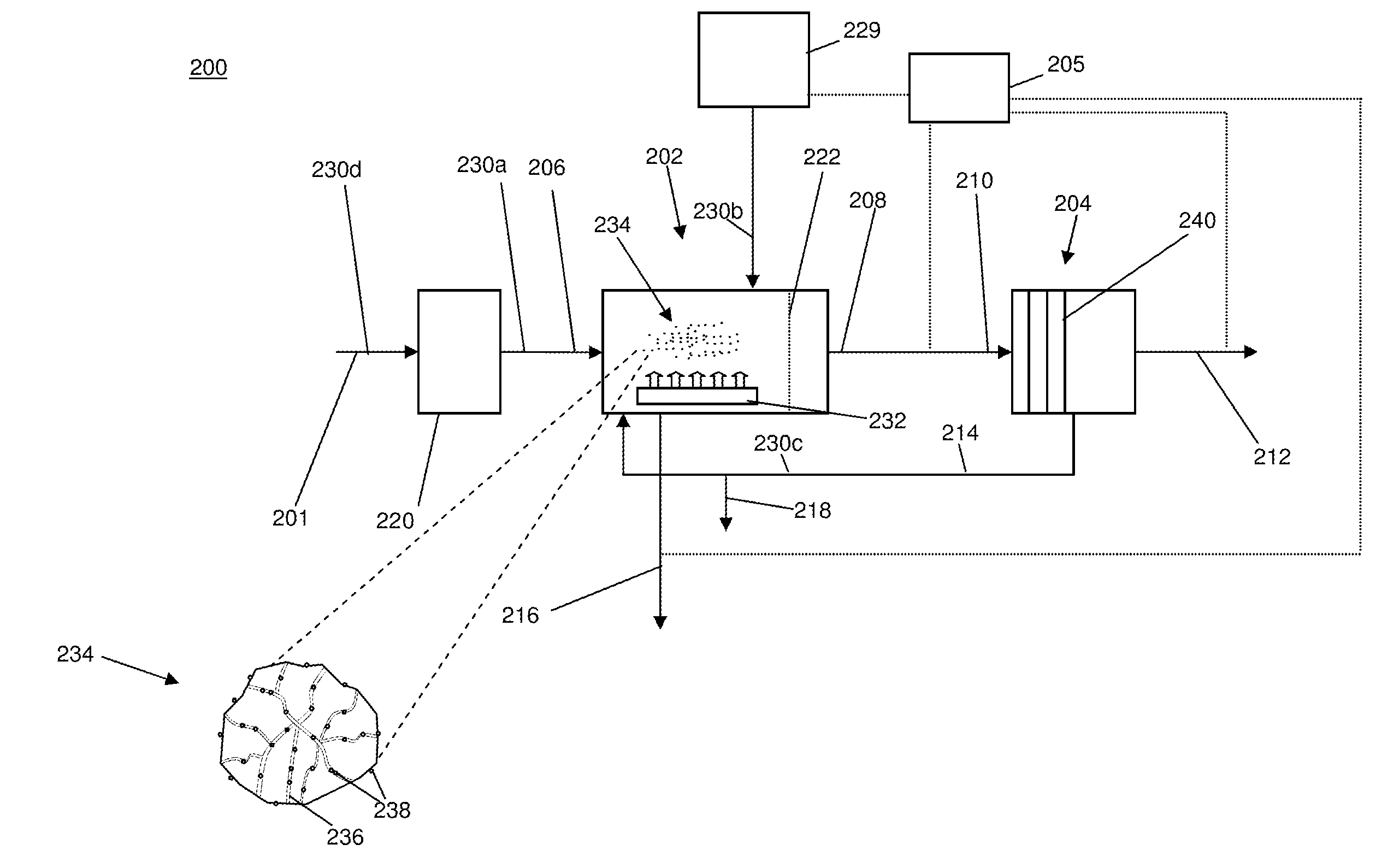
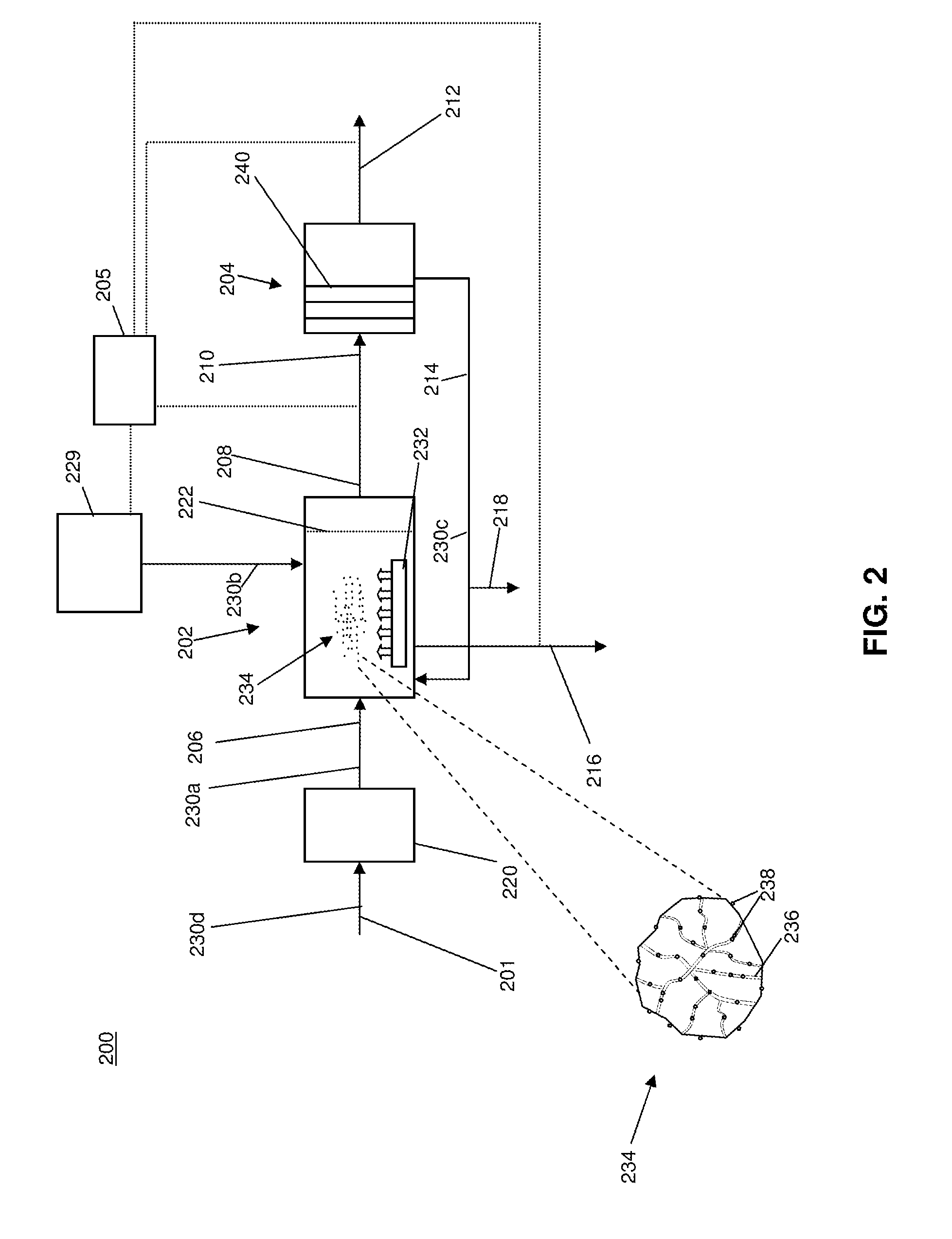
[0202]A granular activated carbon suspension pilot unit was prepared, utilizing a vertical cylindrical tank having a diameter of 1.83 meters (m) (6 feet (ft)) and a water depth of 2.59 m (8.5 ft). One eductor jet nozzle from Siemens Water Technologies (Rothschild, Wis., USA) was installed through an outer wall of the tank at a distance of 43.5 centimeters (cm) (17.125 inches (in)) from the tank floor. The nozzle, shown in FIG. 15, was directed horizontally towards the center of the tank. A 50 mg / l concentration of granular activated carbon, Mead Westvaco Nuchar WVB14×35 / Wood, was introduced into the tank.

[0203]As depicted in FIG. 15, the jet nozzle system included a jet nozzle 1544 which comprised a fluid inlet 1546, a compressed air inlet 1558 and an outlet 1564. Fluid passed from inlet 1546 to a mixing chamber 1566. Compressed air also entered mixing chamber 1566 where it expanded and imparted energy to the fluid. As the air expanded, the mixture of fluid and air passed to a nozzl...


PUM

PropertyMeasurementUnit
specific gravityaaaaaaaaaa

Abstract

A wastewater treatment system is provided comprising a biological reactor having a separation subsystem, a suspension system and a membrane operating system. The separation subsystem is constructed and arranged to maintain adsorbent material in the biological reactor with a mixed liquor. The suspension system is positioned in the biological reactor and is constructed and arranged to maintain adsorbent material in suspension with mixed liquor. The membrane operating system is located downstream of the biological reactor and is constructed and arranged to receive treated mixed liquor from the biological reactor and discharge a membrane permeate. In addition, a wastewater treatment system is provided comprising a first biological reaction zone, a second biological reaction zone and a membrane operating system. The first biological reaction zone is constructed and arranged to receive and treat the wastewater. The second biological reaction zone includes a separation subsystem and is constructed and arranged to receive effluent from the first biological reaction zone. A suspension system for adsorbent material is provided in the second biological reaction zone. The membrane operating system is located downstream of the second biological reaction zone and is constructed and arranged to receive treated wastewater from the second biological reaction zone and discharge a membrane permeate.

Description

RELATED APPLICATIONS[0001]This application claims the benefit of U.S. Provisional Patent Application No. 61 / 224,000 filed Jul. 8, 2009, and U.S. Provisional Patent Application No. 61 / 186,983 filed on Jun. 15, 2009, the disclosures of which are hereby incorporated by reference in their entireties.BACKGROUND OF THE INVENTION[0002]1. Field of the Invention[0003]This invention relates to wastewater treatment systems and methods.[0004]2. Description of Related Art[0005]Effective handling of domestic sewage and industrial wastewater is an extremely important aspect of increasing the quality of life and conservation of clean water. The problems associated with simply discharging wastewater in water sources such as rivers, lakes and oceans, the standard practice up until about a half century ago, are apparent—the biological and chemical wastes create hazards to all life forms including the spread of infectious diseases and exposure to carcinogenic chemicals. Therefore, wastewater treatment ...

Claims


Application Information

Patent Timeline
Patent Type & Authority Applications(United States)
IPC IPC(8): C02F9/14C02F1/44C02F1/28
CPCB01F3/04517B01F5/0212B01F5/10C02F1/283C02F3/006C02F3/08C02F2209/006C02F3/223C02F3/26C02F3/302C02F2101/305C02F2101/363C02F2103/06C02F3/1268C02F3/04C02F3/085C02F3/106C02F3/1263C02F3/2853C02F2101/105C02F2101/16C02F2101/306C02F2101/32C02F2101/345C02F2101/366C02F2103/005C02F2103/20C02F2103/32C02F2203/006C02F2303/24Y02W10/10B01F23/232311B01F25/211B01F25/50C02F9/00C02F1/28C02F1/44C02F3/30B01D15/00C02F3/02C02F2303/18
Inventor CONNER, WILLIAM G.AL-HAJRI, MOHAMMED A.SCHULTZ, THOMAS E.HOWDESHELL, MICHAELFELCH, CHAD L.PATTERSON, MATTHEWSHAFARIK, SAMUELCOOLEY, CURT
Owner SIEMENS ENERGY INC
Learn More