Active oxygen generating device, humidifier, and air purification system with humidifier
a technology of active oxygen and generating device, which is applied in the direction of electrostatic separation details, cells, kettle coolers, etc., can solve the problems of large device, harmful irradiation to the human body, and method consumes a great deal of electrical energy, and achieves the effect of efficient continuous generation of active oxygen
- Summary
- Abstract
- Description
- Claims
- Application Information
AI Technical Summary
Benefits of technology
Problems solved by technology
Method used
Image
Examples
embodiment 1
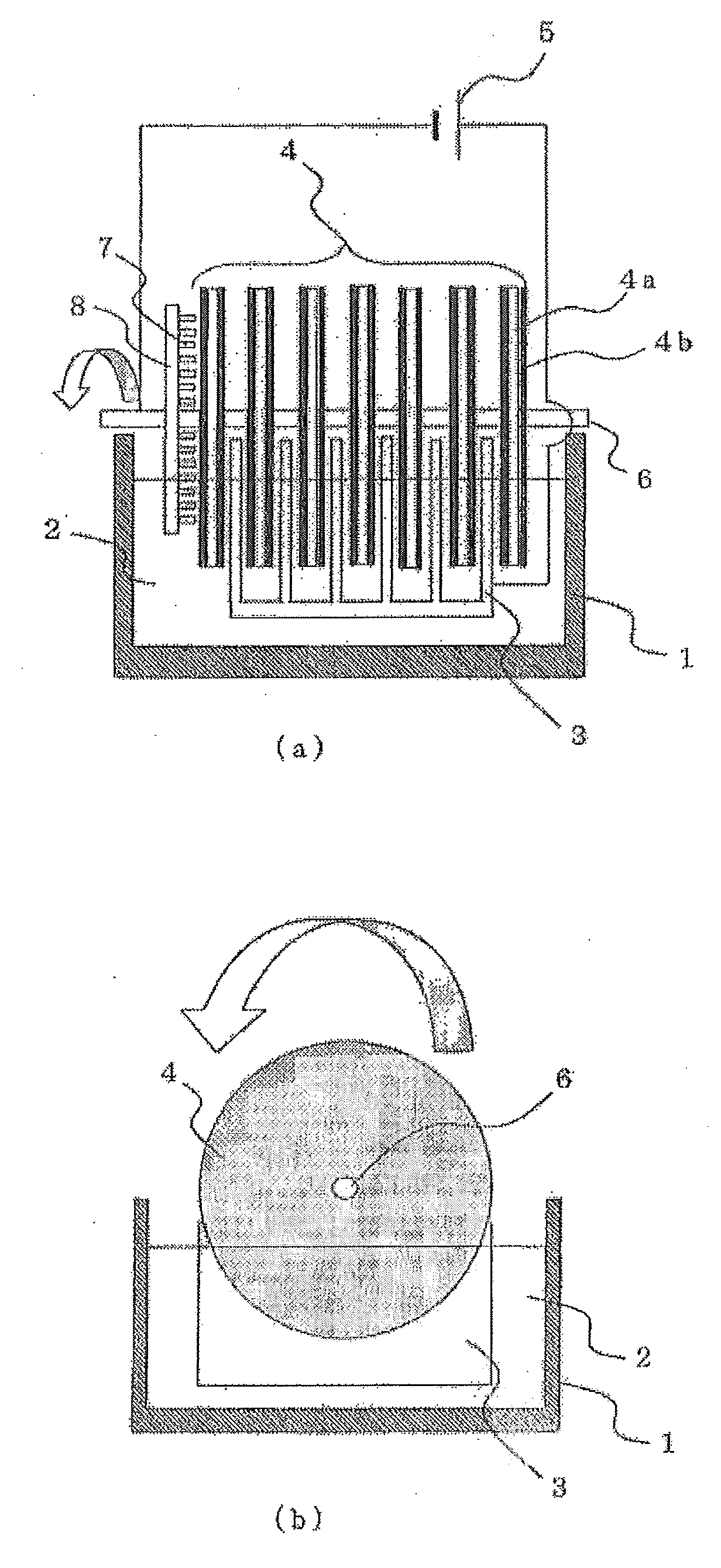
[0025]Descriptions will be given to Embodiment 1 of the present invention using FIG. 1 as follows. FIG. 1(a) is a side view of an active oxygen generating device according to Embodiment 1 of the present invention. FIG. 1(b) is an elevation view.
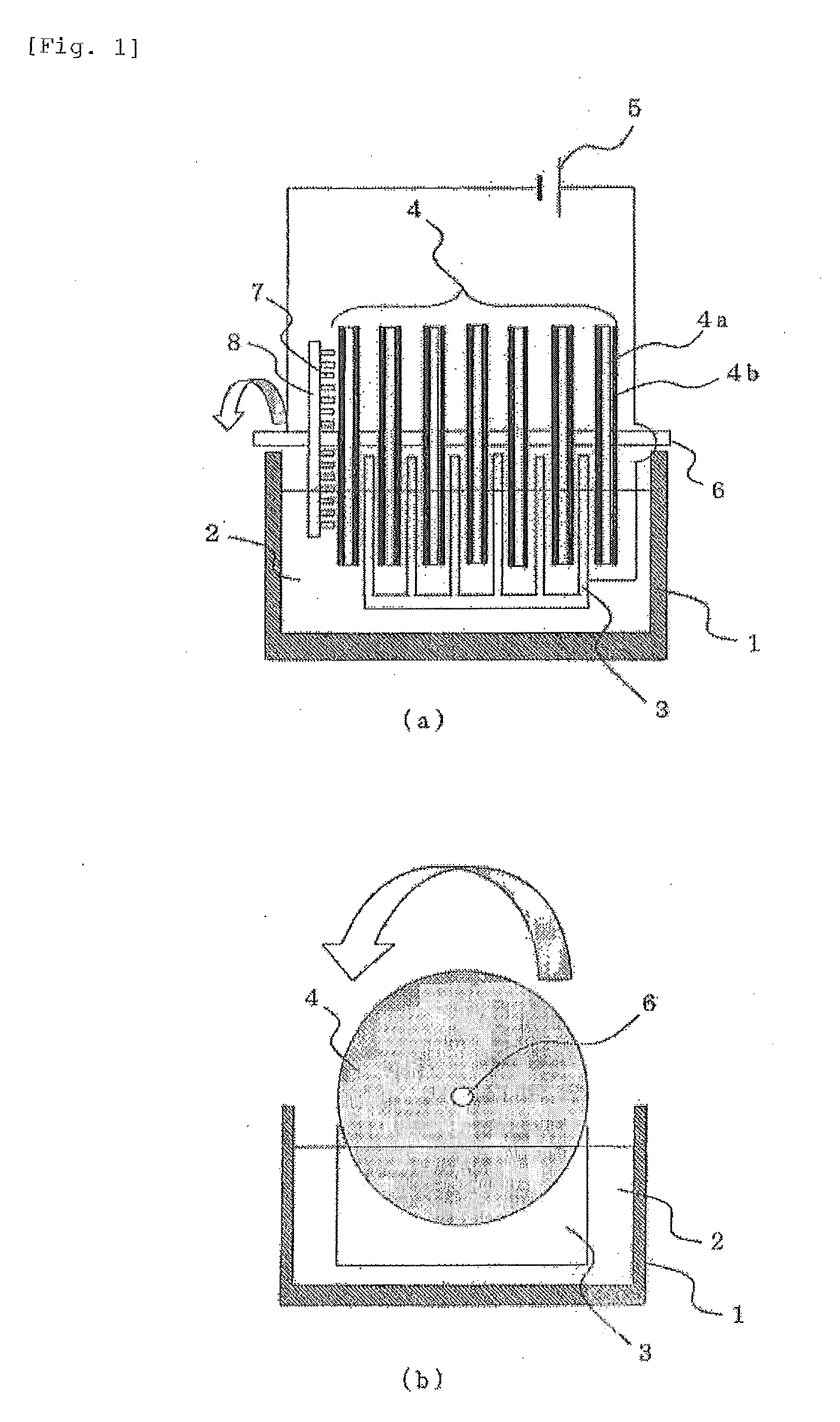
[0026]The active oxygen generating device is composed of a water tank 1, an anode 3 which is installed so as to be partially or totally immersed into the water 2 of the water tank 1, a cathode 4 which is made of a base material 4a containing a conductive polymer 4b and oppositely placed against the anode 3 with a predetermined interval, and a DC power supply 5 such as a battery connected with the anode 3 and the cathode 4. By turning on the electricity between the anode 3 and the cathode 4, the conductive polymer 4b is adapted to deoxidize oxygen dissolved in the water 2 between both electrodes to generate active oxygen. That is, by the conductive polymer 4b contained on the surface of the cathode 3, electrons are supplied to the oxygen disso...
embodiment 2
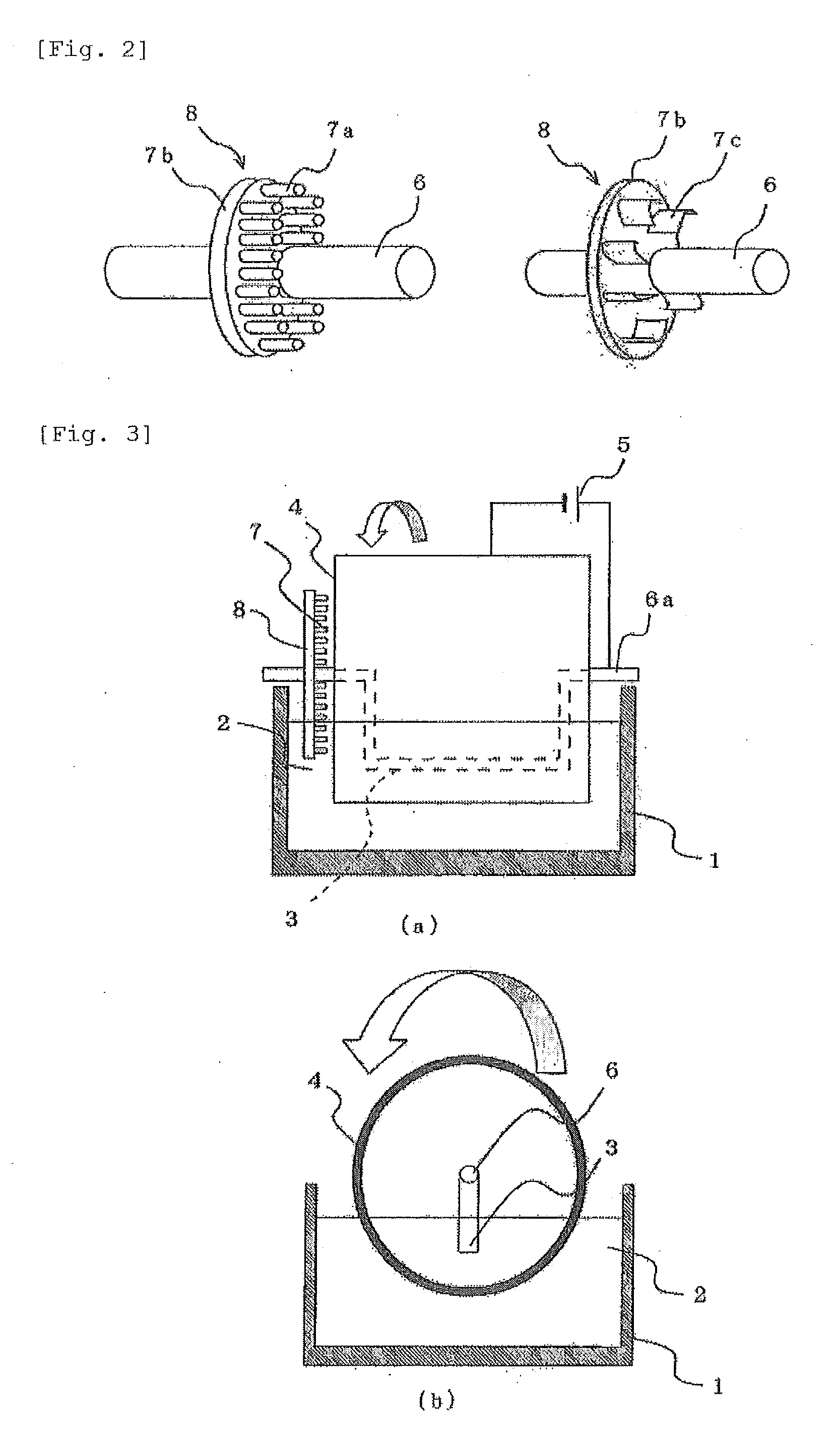
[0036]Descriptions will be given to Embodiment 2 of the present invention using FIG. 3 as follows. FIG. 3(a) is a side view of the active oxygen generating device according Embodiment 2 of the present invention, and FIG. 3(b) is an elevation view.
[0037]Embodiment 2 has a configuration such that a cylindrical or a drum-shaped base material 4a containing the conductive polymer 4b is made to be the cathode 4, a rod-like conductive base material disposed so as to penetrate the center of the cathode is made to be the anode 3, and active oxygen is generated with part (lower part) of the circumference surface being immersed in the water while the cathode 4 rotates, with the upper part of the circumference surface being over the water face, and with electricity being turned on between the cathode and the anode 3. The anode 3 has a concavely bent structure so that a part opposing the cathode 4 is immersed in the water. That is, the anode 3 is a support shaft 6a of the cathode 4 to be a fixed...
embodiment 3
[0039]Descriptions will be given to Embodiment 3 using FIG. 4 as follows. FIG. 4(a) is a side view of the active oxygen generating device according Embodiment 3 of the present invention, and FIG. 4(b) is an elevation view.
[0040]Embodiment 3 has a configuration such that a cylindrical or a drum-shaped base material 4a containing the conductive polymer 4b is made to be the cathode 4, and active oxygen is generated with part (lower part) of the circumference surface being immersed in the water while the cathode 4 rotates, with the upper part of the circumference surface being over the water face, and with electricity being turned on between the cathode and the anode 3 disposed at the bottom face of the water tank 1 under the cathode 4.
[0041]Such a configuration enables to secure a wide area of the cathode 4 immersed in the water against the volumetric capacity of the device to allow much active oxygen production. A distance of 1 to 20 mm is enough between the anode 3 and the cathode 4....
PUM
| Property | Measurement | Unit |
|---|---|---|
| Electrical resistance | aaaaa | aaaaa |
| Temperature | aaaaa | aaaaa |
| Concentration | aaaaa | aaaaa |
Abstract
Description
Claims
Application Information
 - R&D
- Intellectual Property
- Life Sciences
- Materials
- Tech Scout
- Unparalleled Data Quality
- Higher Quality Content
- 60% Fewer Hallucinations
Browse by: Latest US Patents, China's latest patents, Technical Efficacy Thesaurus, Application Domain, Technology Topic, Popular Technical Reports.
© 2025 PatSnap. All rights reserved.Legal|Privacy policy|Modern Slavery Act Transparency Statement|Sitemap|About US| Contact US: help@patsnap.com


