Apparatus and method for injection of a fluid for an exhaust gases treatment device

a technology of exhaust gas treatment device and apparatus, which is applied in the direction of fluid tightness measurement, machines/engines, instruments, etc., can solve the problems of affecting the efficiency of the treatment device, the fluid contained in the system may be subject to degradation, and the injector to become jammed, so as to achieve the effect of less cumbersome and cheap and effectiv

Active Publication Date: 2011-01-27
VOLVO LASTVAGNAR AB
View PDF1 Cites 14 Cited by
  • Summary
  • Abstract
  • Description
  • Claims
  • Application Information

AI Technical Summary

Benefits of technology

[0007]Therefore, there is a need to provide an injection apparatus with a pu...

Problems solved by technology

During those times where the system is inoperative, the fluid contained in the system may be subject to degradation.
For example, the injector is close to the exhaust line and is therefore subject to quite high temperatures.
In case of a system for injecting fuel, the fuel trapped in the injector may be subject to coking, which brings the deposit of carbon substances insid...

Method used


Image

  • Apparatus and method for injection of a fluid for an exhaust gases treatment device
  • Apparatus and method for injection of a fluid for an exhaust gases treatment device
  • Apparatus and method for injection of a fluid for an exhaust gases treatment device

Examples


Embodiment Construction

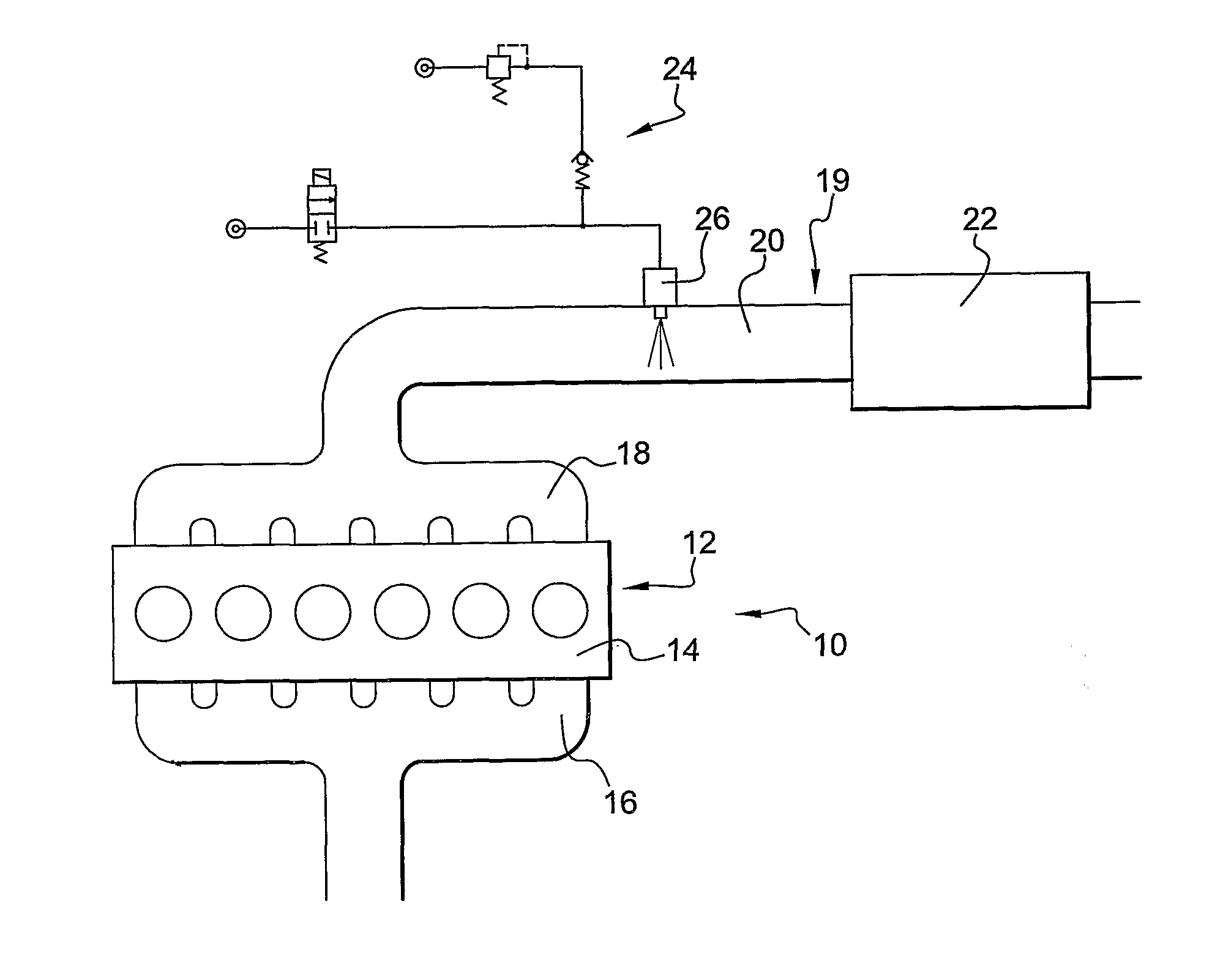
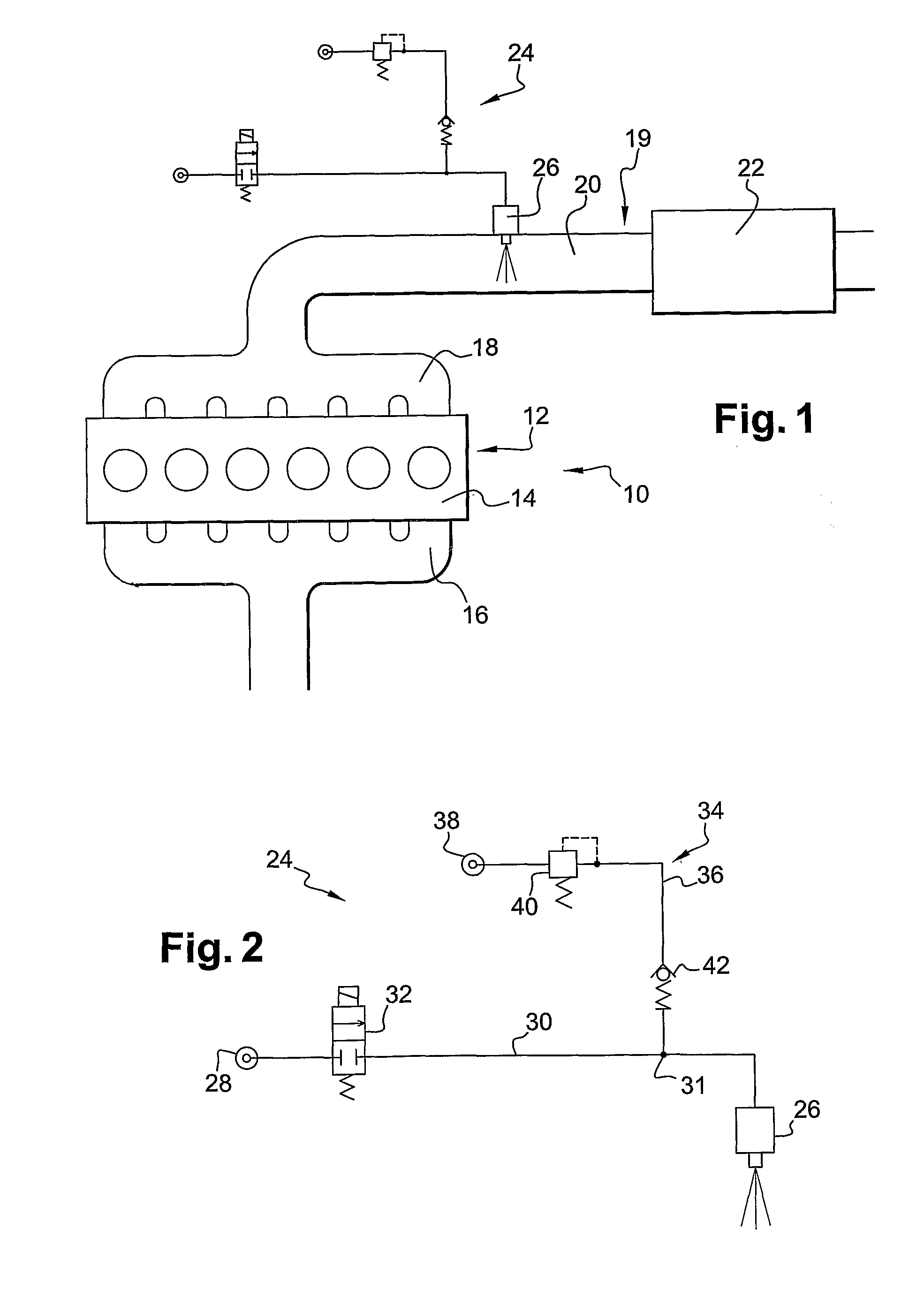
[0020]On FIG. 1 is represented a part of an engine arrangement which can be used for powering a stationary machine, but which can also be fitted for example in a vehicle, such as an industrial truck, or in a machine such as a construction equipment machine.

[0021]The engine arrangement 10 comprises an engine 12, such as a 6 cylinder in-line turbocharged diesel engine. The engine 12 comprises an engine block 14, an intake manifold 16 and an exhaust manifold 18, plus numerous other components not represented on the figure. The exhaust manifold 18 is part of an exhaust line 19 and collects the exhaust gases from the cylinders into at least one exhaust pipe 20. The exhaust line 19 may comprise many other components which are not shown on the figure, such as one or several turbines, an exhaust gas recirculation (EGR) system, an exhaust silencer, etc. On FIG. 1 is represented an exhaust gas treatment device 22 which has the purpose of modifying the chemical composition of the exhaust gases...


PUM

PropertyMeasurementUnit
Pressureaaaaaaaaaa

Abstract

An apparatus is provided for injection of a fluid for an exhaust gases treatment device of an internal combustion engine arrangement. The apparatus includes a fluid injector fed from a source of fluid under pressure through a fluid conduit, a feed valve in the fluid conduit between the source of fluid the said injector, a purge system including a gas conduit connecting a source of pressurized gas to the fluid conduit, a pressure limiter within the gas conduit, and a check valve downstream of the pressure limiter. The pressure limited by the pressure limiter is lower than the pressure of fluid delivered by the source of fluid.

Description

BACKGROUND AND SUMMARY[0001]The invention pertains to the field of apparatus for injection of a fluid for an exhaust gases treatment device of an internal combustion engine arrangement.[0002]It is known to install a Diesel Particulate Filter, or “DPF”, on an exhaust line of a Diesel engine in order to temporally store soot and non-burnt particles present in the exhaust gases of such an engine. Such a DPF must be regularly cleaned by oxidation of the particulate materials. In order to obtain such an oxidation, the temperature of the exhaust gases must be substantially increased. This can be achieved thanks to a burner installed in the exhaust line of the engine next to the DPF. This can also be achieved thanks to an oxidation catalyst installed in the exhaust line, upstream of the DPF. In both cases, fuel is injected in the exhaust line, either to be burnt by the burner or to come into contact with the catalyst. In both cases, the temperature of the exhaust gases increases when they ...

Claims


Application Information

Patent Timeline
IPC IPC(8): F01N3/10B23P19/00G01M3/26
CPCB01D2251/2067F01N3/025F01N3/0253F01N3/2066F01N11/00Y10T29/51F01N2610/03F01N2610/08F01N2610/1493Y02T10/47Y02T10/24F01N2240/14F01N2550/05Y02T10/12Y02T10/40
Inventor GAUDIN, BRUNOHEDNA, MOURADMEIER, PHILIPMARSDEN, JAMES E.
Owner VOLVO LASTVAGNAR AB
Why Eureka
Try Eureka