
Automotive door check with energy storage body

Active Publication Date: 2011-01-27
MULTIMATIC INC
View PDF16 Cites 22 Cited by
  • Summary
  • Abstract
  • Description
  • Claims
  • Application Information

AI Technical Summary

Benefits of technology

[0006]Accordingly, it would be advantageous to create an automotive door check apparatus that provides identical functional performance to the prior art configurations but does so with fewer components and moving parts than these existing arrangements.
[0007]The present invention reduces the complexity, weight and cost of an automotive door check apparatus by combining the functions of the check housing and mounting bracket with that of the energy storage device. This combining of functions eliminates the requirement for separate springs, multiple piece check housings and ball bearings, rollers or sliders as utilized by the prior art devices. The door check apparatus of the present invention is reduced to two moving parts from a minimum of seven in the prior art arrangements.
[0011]In a further aspect of the present invention the check arm is configured with a bump stop that is adapted to pass through the guidance arrangement of the unitary check body with no contact. The vehicle door is prevented from further rotation at its full open swing limit by the bump stop contacting the unitary check body at its mounting face. In this manner the stop loads associated with preventing further rotation of the vehicle door are transferred directly to the vehicle door structure rather than through the unitary check body. This allows the unitary check body to be optimized for the single function of generating the predetermined checking forces via the compliant leaves rather than also being required to carry full open stop loads. This bump stop arrangement is a primary differentiator over the prior art in which the check housings are configured to withstand the full open swing limit stop loads.
[0012]In a preferred embodiment of the present invention an energy absorber is incorporated into the bump stop of the check arm so that when it contacts the backside of the mounting face of the unitary check body the kinetic energy carried by the moving vehicle door is dissipated. By dissipating the kinetic energy in a controlled manner the vehicle door is prevented from bouncing closed when it reaches the full open swing limit.
[0013]In an additional aspect of the present invention the check arm is adapted to accept a paint clip device that is configured with additional detent features and cam surfaces. The paint clip device is configured to provide additional check positions as required during the paint and assembly process of the vehicle. The paint clip device is configured to be easily removable from the check arm after the paint and assembly process. In this way the automotive door check apparatus of the present invention is capable of providing a temporary check position at the vehicle door full closed limit to facilitate painting prior to the door latch being installed.
[0021]f) the mounting bracket is rigidly mounted to the vehicle body via bolting, welding, bonding, riveting or similar fastening means;such that rotary motion of the vehicle door relative to the vehicle body structure is checked with predetermined forces generated from the energy stored and released by the compliant leaves of the unitary check body, at positions determined by the relationship between the detent features of the check arm relative to the guidance arrangement, and the vehicle door is prevented from further rotation at its full open swing limit by the bump stop feature contacting the unitary check body at its mounting surface so that stop loads associated with preventing further rotation are transferred directly to the vehicle door structure, and the vehicle door is prevented from bouncing closed by the energy absorbing material.

Problems solved by technology

Because the automotive door check apparatus must be located between the vehicle's body structure and door, it is forced to occupy a severely restricted package space as there is limited clearance between the vehicle body structure and the door and very little volume available within the door.

Method used


Image

  • Automotive door check with energy storage body
  • Automotive door check with energy storage body
  • Automotive door check with energy storage body

Examples


Embodiment Construction

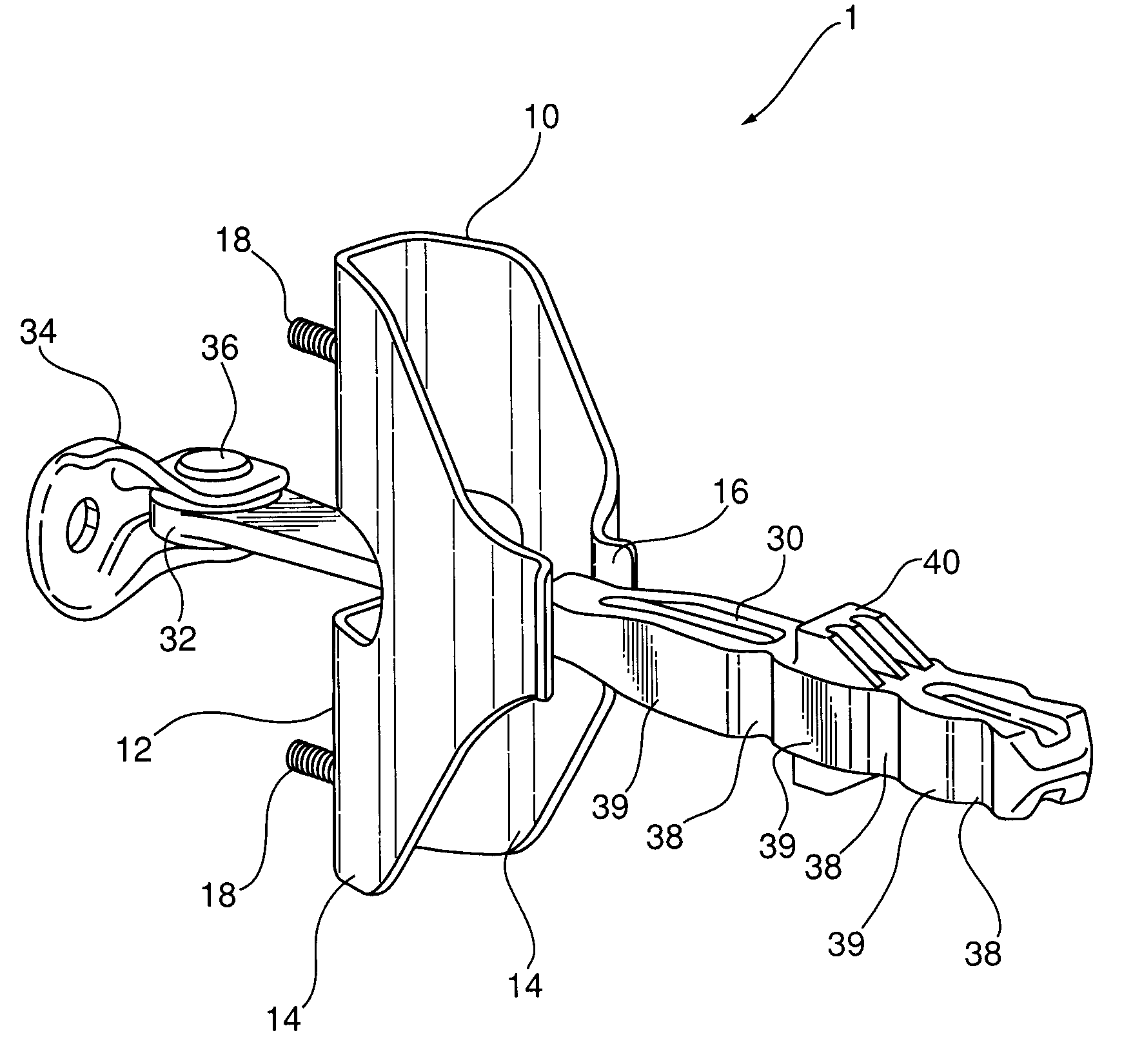
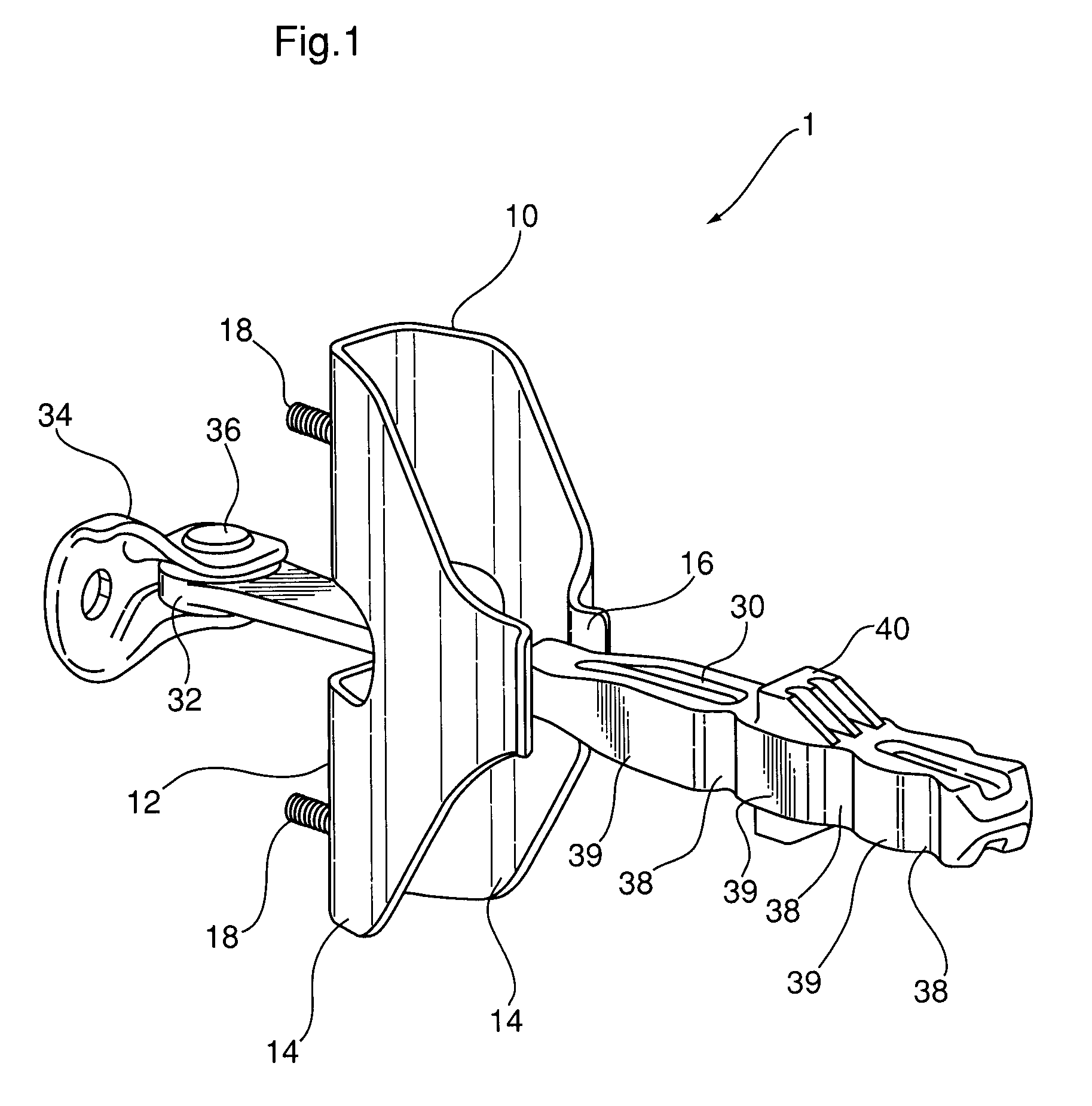
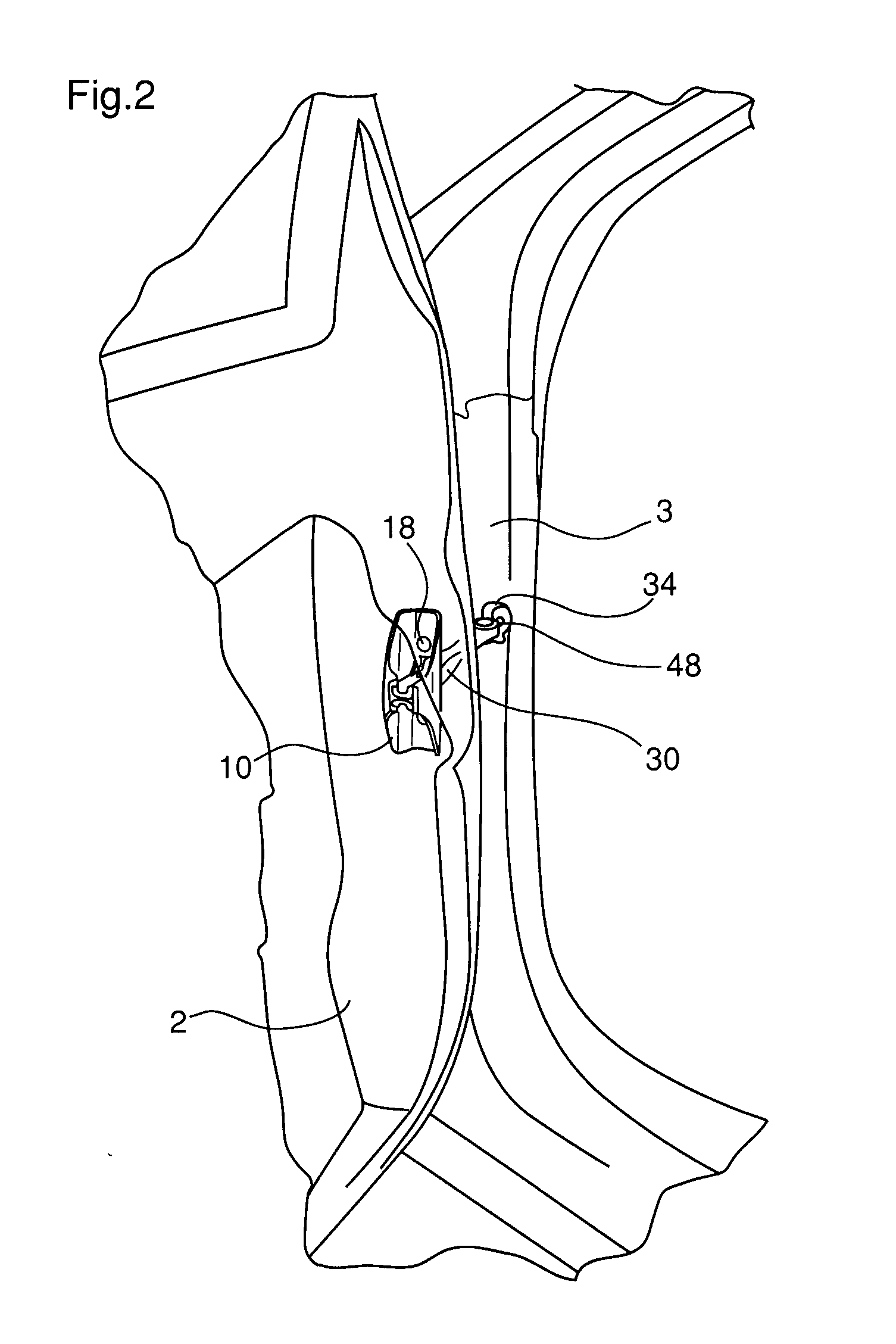
[0032]Referring to FIGS. 1 and 3, an automotive door check apparatus (1) consists of a unitary check body (10) and a check arm (30). The unitary check body (10) is configured with a mounting face (12), a pair of compliant leaves (14), a guidance arrangement (16) and at least one mounting fastener (18). The check arm (30) is configured with a pivot boss (32), a mounting bracket (34), a pivot rivet (36), detent features (38), cam surfaces (39) and a bump stop (40). Referring to FIGS. 1 and 2, the unitary check body (10) is adapted to rigidly attach to a vehicle door (2) via its at least one mounting fastener (18). The check arm (30) is adapted to rigidly mount to a vehicle body structure (3) via its mounting bracket (34) and at least one attachment fastener (48). The check arm (30) is configured to rotate around its pivot rivet (36) and to move through the unitary check body (10) and slideably interface with the guidance arrangement (16).

[0033]Relative rotary motion between the vehicl...


PUM


Abstract

A door check apparatus for an automobile comprises a unitary check body containing a pair of compliant leaves and a guidance arrangement which is adapted to be rigidly mounted to a vehicle door. It also comprises a check arm containing cam surfaces and detent features which is pivotally connected to a vehicle body structure and is configured to slideably interface with the guidance arrangement of the unitary check body. The unitary check body is manufactured from a resilient material so that the compliant leaves are capable of storing and releasing energy in response to the movement of the cam surfaces and detent features of the check arm relative to the guidance arrangement. Rotary motion of the vehicle door relative to the vehicle body structure is checked with predetermined forces generated from the energy stored and released by the compliant leaves at positions determined by the relationship between the detent features of the check arm relative to the guidance arrangement of the unitary check body.

Description

FIELD OF THE INVENTION[0001]This invention relates to automotive door check devices, and in particular to a compact mechanical device capable of holding an automotive door in a number of predetermined open positions with a predetermined force.DESCRIPTION OF THE PRIOR ART[0002]It has been found useful to check the movement of an automotive door in a number of predetermined open positions to assure convenient and safe ingress / egress of the occupants. The door is normally checked against movement in at least one open position with an effort or resistive force adequate to resist wind gusts and the effect of parking on an incline or grade.[0003]The most common form of automotive door check apparatus is a mechanical device that resists motion by releasably storing energy in response to forced motion of the system. These devices, located between the vehicle's body structure and door, can be configured to be integral with the door hinge or separate as autonomous mechanical assemblies. Energ...

Claims


Application Information

Patent Timeline
IPC IPC(8): E05F5/06
CPCY10T16/625Y10T16/61Y10T16/6295E05C17/203E05C21/005B60J5/00E05B17/22
Inventor NG, BILLY CHEAN WANG
Owner MULTIMATIC INC
Learn More