
Interlocking type plastic tile structure

a plastic tile and interlocking technology, applied in the direction of construction, covering/lining, building components, etc., can solve the problems of high manufacturing cost, oblique plastic tile obliqueness, and poor so as to reduce the manufacturing cost of plastic tiles and facilitate construction. , the effect of good alignment of two plastic tiles

Inactive Publication Date: 2011-01-20
WIN TON PLASTICS IND
View PDF6 Cites 32 Cited by
  • Summary
  • Abstract
  • Description
  • Claims
  • Application Information

AI Technical Summary

Benefits of technology

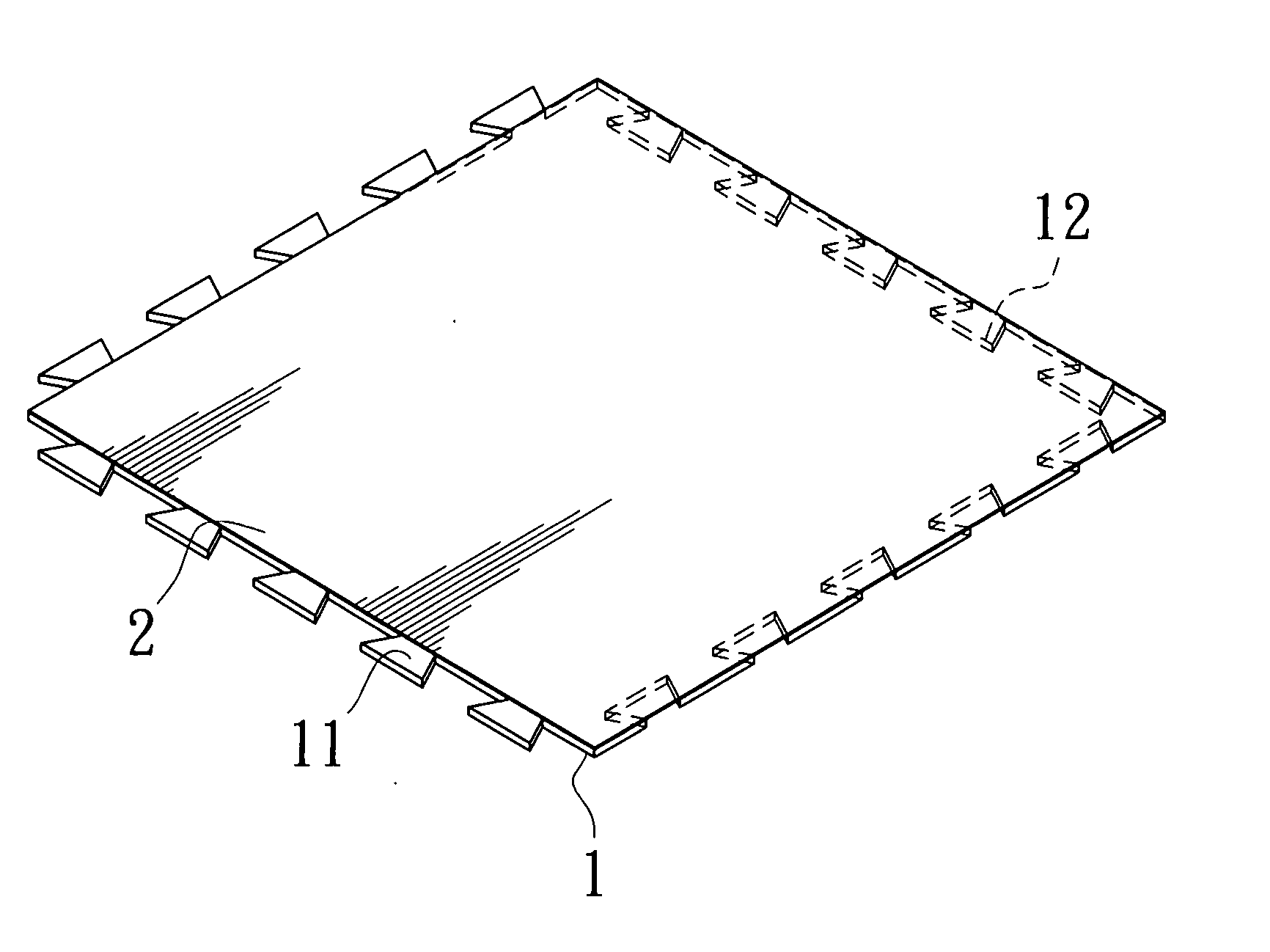
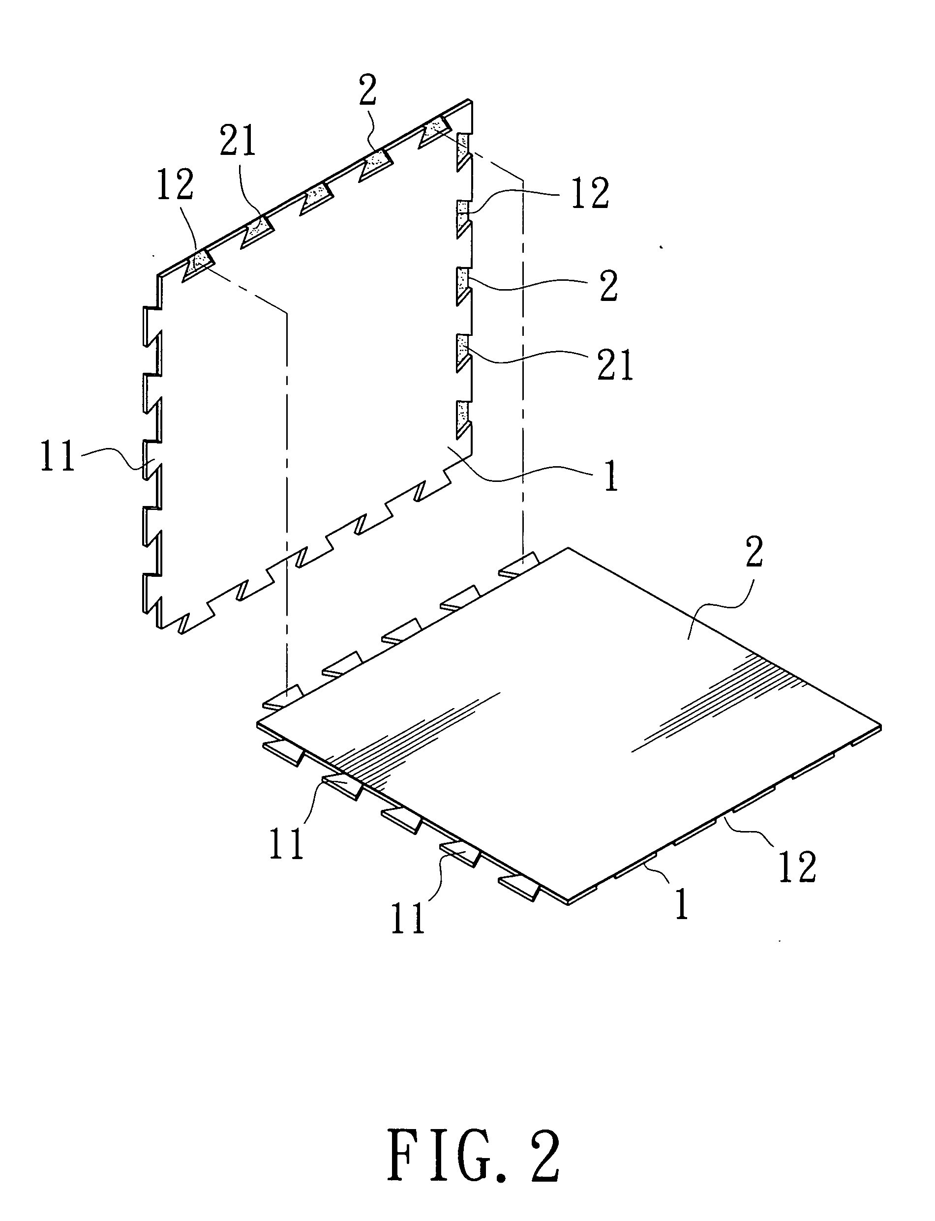
The present invention is an interlocking type plastic tile structure that aims to reduce manufacturing costs, improve alignment between tiles, and eliminate the need for adhesive coating on the floor. The surface layer of the tiles is coated with adhesive and combined with a PVC base layer in contact with the floor. Protruding tongues and notches are formed on the PVC base layer, allowing for interlocking and alignment between tiles. The interlocking type plastic tile structure can be used with various patterned surfaces, such as stone material leather, wood material leather, ceramic tile, cured resin coating, printed plastic baseboard, pure plastic tile, rubber tile, bamboo straw mat, wood tile, and stone material tile, to enhance its aesthetic appeal. The upper surface of the interlocking type plastic tile structure can also be provided with a transparent protective layer for added protection.

Problems solved by technology

However, the plastic tiles are apt to become oblique during adhesion by this method.
1. The protruding portions of the surface layer and the base layer are bigger in areas; this will cause bigger allowance of adhering two plastic tiles together so that there is bad alignment on plastic tiles. Eventually, the entire floor is not beautiful.
2. Release paper for protection purpose has to be provided on the protruding portion of the base layer having bigger area when manufacturing the plastic tile. Thus, manufacturing cost is high in this case.

Method used


Image

  • Interlocking type plastic tile structure
  • Interlocking type plastic tile structure
  • Interlocking type plastic tile structure

Examples


Embodiment Construction

[0024]The technical content, objects and effectiveness of the present invention will become more apparent by the detailed description of a preferred embodiment of the present invention in conjunction with the accompanying drawings.

[0025]Firstly referring to FIGS. 1 to 4 showing a perspective appearance and a schematic exploded assembly view of the interlocking type plastic tile structure of the present invention, in which the plastic tile comprises:

[0026]a PVC base layer (1), being a base layer contacted with floor, the PVC base layer (1) can be a rigid PVC material in which a plurality of protruding tongues (11) and notches (12) are provided at respective two adjacent sides;

[0027]a surface layer (2), the lower surface of which is coated with adhesive (21) so as to be adhered with the PVC base layer (1), the adhesive (21) being exposed to the outside at the notches (12) for the purpose of adhering with the corresponding protruding tongue (11) on the PVC base layer (1) of the next pl...


PUM

PropertyMeasurementUnit
transparentaaaaaaaaaa
shapeaaaaaaaaaa
adhesionaaaaaaaaaa

Abstract

This invention relates to an interlocking type plastic tile structure in which the surface layer having a pattern thereon is coated with adhesive and then is combined with a PVC base layer adhered to the floor. A plurality of protruding tongues and a plurality of notches are respectively formed on two adjacent sides of the PVC base layer. With this structure, when two such plastic tiles are interlocked with respect to each other, the notches having adhesive layer are interlocked and adhered with the protruding tongues correspondingly so as to achieve assembly and good alignment. Besides, there is no need for providing release paper, therefore cost can be saved and assembly is very convenient.

Description

BACKGROUND OF THE INVENTION[0001]1. Field of the Invention[0002]This invention relates to an interlocking type plastic tile structure, especially to an interlocking type plastic tile structure which is simple in assembling and precise in insertion and alignment by the formation of protruding tongues and notches capable of interlocking.[0003]2. Brief Description of the Prior Art[0004]The adhering structure of ordinary plastic tile, as shown in FIG. 5, substantially has printed layer between a main body (51) and a transparent leather (54), and the printed layer further includes a PVC leather material (52) and a printed pattern layer (53). The main body (51) is essentially formed by the mixing of PVC powder, calcium carbonate and toughening agent (DOP). The printed pattern layer (53) can be printed either on the bottom face of the transparent leather (54) or on the surface of the PVC leather material (52). Hot pressing is conducted on the main body (51), the PVC leather material (52), ...

Claims


Application Information

Patent Timeline
Patent Type & Authority Applications(United States)
IPC IPC(8): E04C2/38E04C2/20E04C2/26
CPCE04F15/10E04F2203/06E04F2201/095E04F2201/07
Inventor SHEN, CHI-FENG
Owner WIN TON PLASTICS IND
Learn More