Capacitor forming method
a technology of capacitors and forming methods, applied in the manufacture of capacitors, fixed capacitor details, cell components, etc., can solve the problems of difficult “capture glass”, glass shatters into small pieces, and the inability to form useful glass shapes by quenching
- Summary
- Abstract
- Description
- Claims
- Application Information
AI Technical Summary
Benefits of technology
Problems solved by technology
Method used
Image
Examples
third embodiment
[0029]After forming a useful glass-metal shape near the working point temperature for a ferroelectric glass, the heat soaking process can begin immediately to begin growing ferroelectric crystals. Annealing to room temperature would now start for a glass not intended to be devitrified. However, for a glass intended for devitrification, a slow heat-soak, perhaps lasting several hours, may be needed to grow the necessary small microcrystals within the glass. For example, in the method, described below, the heat soaking process can begin on a production roller kiln as soon as the laminate is formed. After some devitrification to gain stiffness, cutting the flat laminate into pieces with a laser would then permit stacking of these pieces on kiln cars that pass through a large tunnel kiln, as would be needed to complete the heat-soaking process. After heat soaking, the laminated product should be slowly cooled to room temperature by moving the loaded car in the tunnel kiln directly into ...
first embodiment
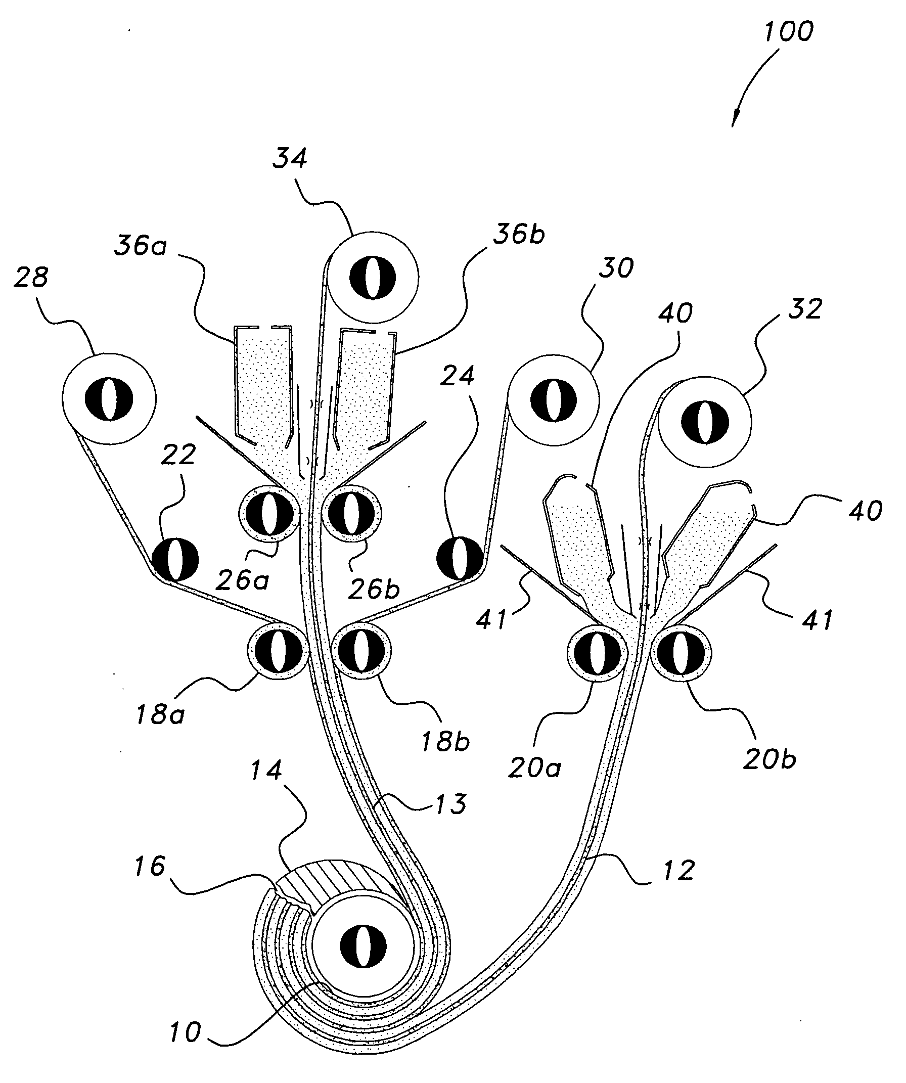
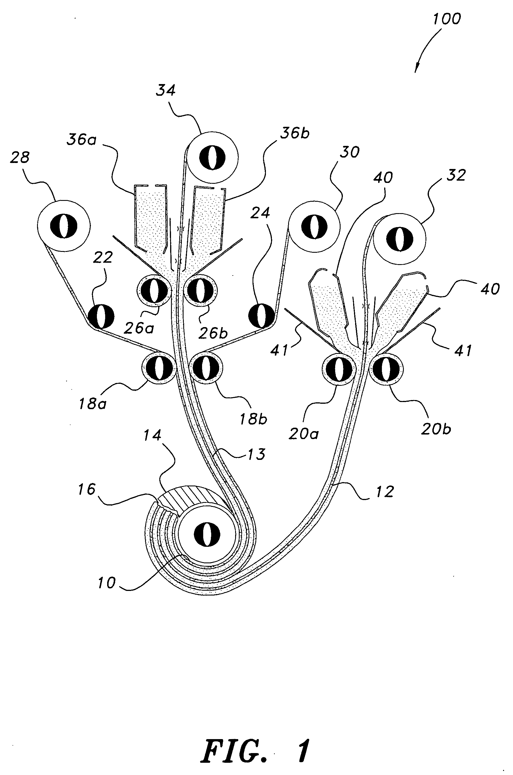
[0044]In the capacitor forming method, as shown in FIG. 1, a lowest point spool 10 takes up a three metal foil-two glass layer composite ribbon 13 while concurrently taking up a ribbon 12 comprising a single metal foil coated on both sides with glass. Preferably the spool 10 has an outer thin ceramic ramp surface 14. The ribbons 12 and 13 being spooled by lowest point spool 10 are insulated and held together by an adhesive 16, preferably Sauereisen cement No.1.
[0045]Ribbon 12 originates from a spool 32 that is disposed above movable hot glass cartridges 40. Liquid glass flowing out of glass cartridges 40 is pressed onto the metal ribbon by rollers 20a and 20b to form the coated ribbon 12. The liquid glass is constrained by platinum bin 41, which funnels the liquid glass proximate the glass pressing location.
[0046]The composite ribbon 13 includes a central metal foil component that originates from spool 34 above removable or moving hot glass cartridges 36a and 36b. The volume of visc...
PUM
| Property | Measurement | Unit |
|---|---|---|
| temperature | aaaaa | aaaaa |
| viscosity | aaaaa | aaaaa |
| viscosity | aaaaa | aaaaa |
Abstract
Description
Claims
Application Information
 - R&D Engineer
- R&D Manager
- IP Professional
- Industry Leading Data Capabilities
- Powerful AI technology
- Patent DNA Extraction
Browse by: Latest US Patents, China's latest patents, Technical Efficacy Thesaurus, Application Domain, Technology Topic, Popular Technical Reports.
© 2024 PatSnap. All rights reserved.Legal|Privacy policy|Modern Slavery Act Transparency Statement|Sitemap|About US| Contact US: help@patsnap.com


