
Hydrogen generator

a hydrogen generator and generator technology, applied in the field of hydrogen generators, can solve the problems of reducing energy density, fuel cell using such a tank is not suitable for portable power sources, and the reliability of lithium ion secondary batteries is not yet reliable enough to ensure a continuous available time, etc., and achieves the effect of generating hydrogen in a simple manner

Inactive Publication Date: 2011-01-13
HITACHI MAXELL ENERGY LTD
View PDF9 Cites 7 Cited by
  • Summary
  • Abstract
  • Description
  • Claims
  • Application Information

AI Technical Summary

Benefits of technology

[0013]Therefore, with the foregoing in mind, it is an object of the present invention to provide a hydrogen generator that is capable of generating hydrogen efficiently in a simple manner.
[0015]According to the present invention, a hydrogen generator capable of generating hydrogen efficiently in a simple manner can be provided.

Problems solved by technology

However, depending on the type of cordless equipment to be used, the lithium ion secondary battery is not yet reliable enough to ensure a continuous available time.
Although there are several candidates for fuels used for the fuel cells, the individual fuels have various problems, and a final decision has not been made yet.
However, a fuel cell using such a tank is not suitable for a portable power source, since both the volume and the weight of the fuel cell are increased, and the energy density is reduced.
However, a fuel cell using hydrocarbon fuel requires a reformer and thus poses problems such as supply of heat to the reformer and thermal insulation.
Therefore, this fuel cell is not suitable for a portable power source either.
However, according to the method as described in Patent Document 1, hydrogen cannot he generated without addition of at least 15 weight % of calcium oxide with respect to the total amount including the aluminum.
Moreover, the hydrogen generation rate fluctuates considerably over the reaction time, and it will cause serious problems in view of the efficiency and stability of hydrogen generation reaction.
Similarly, according to the method as described in Patent Document 2, a large amount of additives are required to advance the hydrogen generation reaction efficiently, and thus the Patent Document 2 cannot provide a method for generating hydrogen in an efficient and stable manner.
However, it has been clarified that even the techniques as disclosed in Patent Documents 3 and 4 are still susceptible to improvement in the structure of the vessel containing the hydrogen generating material, from the viewpoint of improving the hydrogen generation efficiency

Method used


Image

  • Hydrogen generator
  • Hydrogen generator
  • Hydrogen generator

Examples


example 1

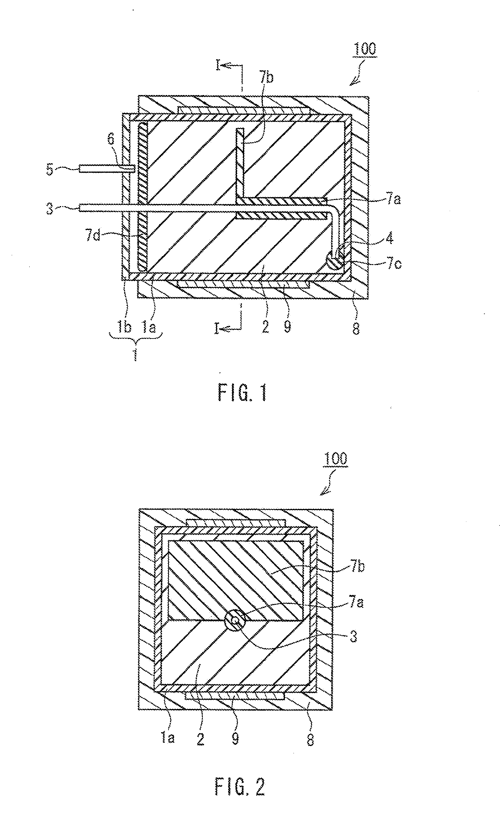
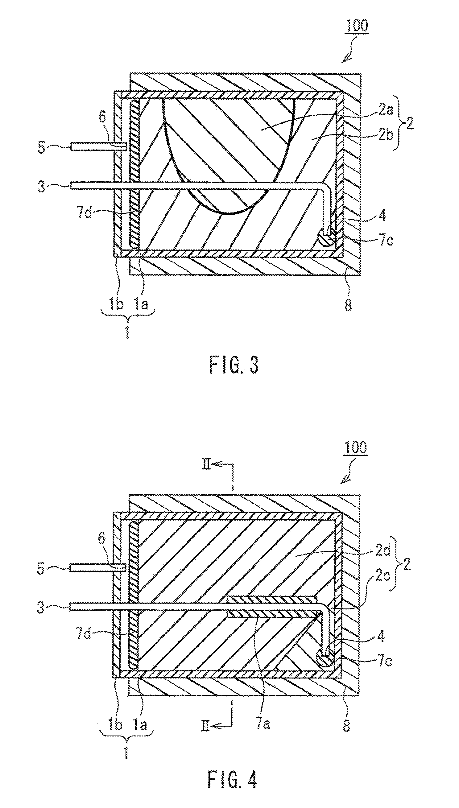
[0082]Hydrogen was produced in the following manner by using the fuel cartridge 100 as a hydrogen generator of the present invention as shown in FIG. 4. FIG. 5 is a cross-sectional view taken along a line II-II in FIG. 4. In FIGS. 4 and 5, components identical to those in FIGS. 1 and 2 are assigned with identical signs for avoiding duplication of the description. This applies also to FIGS. 6 to 10 below.

[0083]A hydrogen generating material A was prepared by mixing in a mortar 1.0 g of aluminum powder as a metallic material having a mean particle diameter of 6 μm and 1.0 g of calcium oxide powder as an exothermic material having a mean particle diameter of 3μm. Further, a hydrogen generating material B was prepared by mixing in a mortar 98.5 g of the aluminum powder as a metallic material and 12.5 g of the calcium oxide powder as an exothermic material.

[0084]Next, 2 g of the hydrogen generating material A (2c in FIGS. 4) and 111.0 g of the hydrogen generating material B (2d in FIG. 4...

examples 2-3

[0089]A hydrogen generator was manufactured in the same manner as Example 1 except that absorbent cotton as the water absorbent 7a was disposed on the periphery of the water supply pipe 3 in accordance with the disposing condition as shown in Table 1. Subsequently, hydrogen was generated in the same manner as Example 1 and the reaction rate was measured.

example 4

[0090]A hydrogen generator was manufactured in the same manner as Example 1 except that 0.2 g of absorbent cotton as a water absorbent 7b was disposed as shown in FIGS. 6 and 7. Namely, in FIGS. 6 and 7, the water absorbent 7b extends further from the end part of the water absorbent 7a positioned opposite to the above-mentioned reference plane toward the wall surface of the vessel 1 positioned in the upper region, and the water absorbent 7b is not in contact with the wall surface. Subsequently, hydrogen was generated in the same manner as Example 1 and the reaction rate was measured. FIG. 6 is a schematic cross-sectional view of a fuel cartridge used in the present Example, and FIG. 7 is a cross-sectional view taken along a line III-III in FIG. 6.


PUM

PropertyMeasurementUnit
Fractionaaaaaaaaaa
Fractionaaaaaaaaaa
Fractionaaaaaaaaaa

Abstract

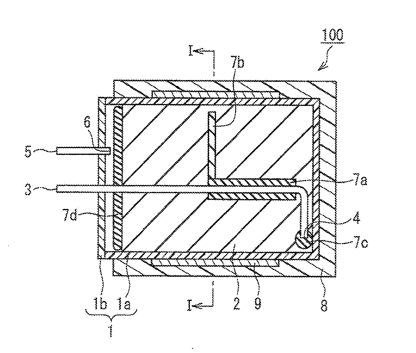
A hydrogen generator of the present invention has a vessel for containing a hydrogen generating material including a metallic material for generating hydrogen by an exothermic reaction with water. The vessel includes a water supply pipe for supplying water into the vessel and a hydrogen outlet for discharging hydrogen generated in the vessel to the outside of the vessel. In the hydrogen generator, a wall surface of the vessel facing the hydrogen outlet is set as a reference plane, a water supply port at the end of the water supply pipe disposed inside the vessel is disposed in the vicinity of the reference plane, the water supply pipe includes a perpendicular portion extending from the vicinity of the center of the reference plane in a direction perpendicular to the reference plane, and a water absorbent is disposed on the periphery of the perpendicular portion of the water supply pipe and not disposed on a portion of 15% or more of an effective length of the perpendicular portion on the hydrogen outlet side.

Description

TECHNICAL FIELD[0001]The present invention relates to a hydrogen generator using a metallic material that reacts with water so as to generate hydrogen.BACKGROUND ART[0002]With the recent widespread use of cordless equipment such as a personal computer or a portable telephone, secondary batteries used as a power source of cordless equipment are increasingly required to have a smaller size and higher capacity. At present, a lithium ion secondary battery that can achieve a small size, light weight, and high energy density is being put to practical use and growing in demand as a portable power source. However, depending on the type of cordless equipment to be used, the lithium ion secondary battery is not yet reliable enough to ensure a continuous available time.[0003]Under these circumstances, a polymer electrolyte fuel cell has been studied as an example of a battery that may meet the above requirements. The polymer electrolyte fuel cell uses a solid polymer electrolyte as its electro...

Claims


Application Information

Patent Timeline
IPC IPC(8): B01J19/00B22F1/068B22F1/16
CPCB22F1/0007B22F1/0055B22F1/02C01B3/065Y02E60/50H01M8/04208H01M8/04216H01M8/065Y02E60/362C01B3/08Y02E60/36B22F1/068B22F1/16
Inventor MIKI, TAKESHINAKAI, TOSHIHIROSAIBARA, SHOJI
Owner HITACHI MAXELL ENERGY LTD
Learn More