
Temporary locking of an electronic circuit

Active Publication Date: 2011-01-13
PROTON WORLD INT
View PDF36 Cites 18 Cited by
  • Summary
  • Abstract
  • Description
  • Claims
  • Application Information

AI Technical Summary

Benefits of technology

[0011]At least one embodiment of the present invention aims at overcoming all or part of the disadvantages of known mechanisms of protection against lacks of authentication.
[0012]An embodiment aims at an authentication mechanism which avoids the need to replace the involved electronic circuits.
[0013]An embodiment aims at a solution avoiding implementation of an unlocking process by the circuit provider.

Problems solved by technology

Authentication mechanisms generally do not enable making the difference between the keying in of too many codes in a fraud attempt or when the user has forgotten his code.
Such a solution is expensive since the card is disposed of.

Method used


Image

  • Temporary locking of an electronic circuit
  • Temporary locking of an electronic circuit
  • Temporary locking of an electronic circuit

Examples


Embodiment Construction

[0052]The same elements have been designated with the same reference numerals in the different drawings.

[0053]For clarity, only those elements and steps which are useful to the understanding of the present invention have been shown in the drawings and will be described hereafter. In particular, the actual code transmission and signature calculation mechanisms have not been illustrated, the present invention being compatible with usual mechanisms. Similarly, the actions taken by the electronic devices after an authentication error have not been detailed, the present invention being here again compatible with usual actions.

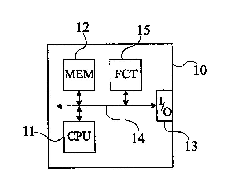
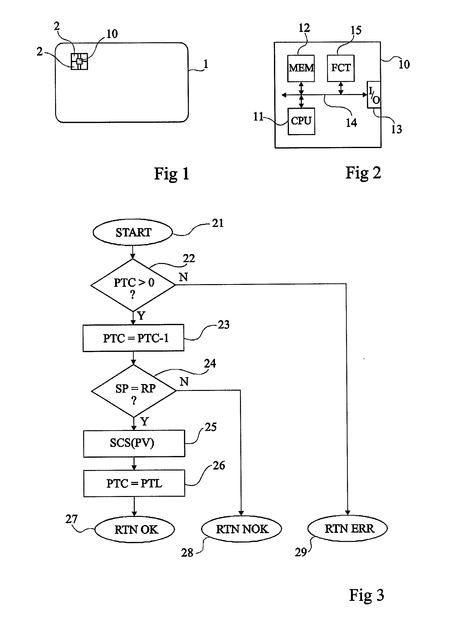
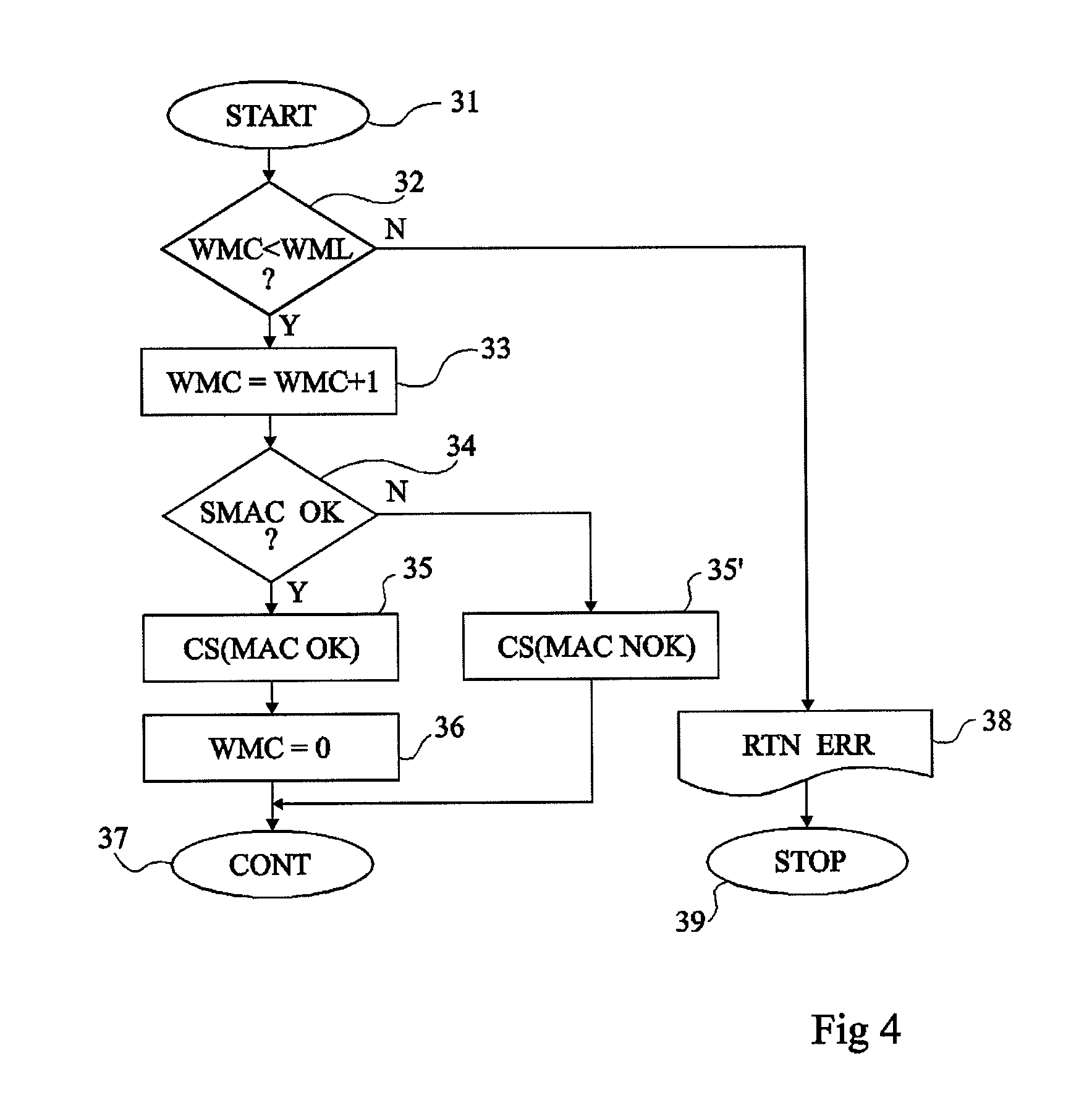
[0054]FIG. 1 schematically shows a smart card 1 of the type to which the present invention applies as an example. Such a card is formed of a support, generally made of plastic matter, on or in which are embedded one or several electronic circuits 10. Circuit 10 is capable of communicating with a terminal by means of contacts 2 and / or without contact (radioelectric t...


PUM


Abstract

A method and a circuit for protecting at least one piece of information contained in an electronic circuit by disabling at least one function of the circuit in case of detection of a number of abnormal operations greater than a threshold, in which the disabling of the function is temporary, of a duration independent from whether the circuit is powered or not.

Description

CROSS REFERENCE TO RELATED APPLICATIONS[0001]This application claims the priority benefit of French patent application number 07 / 52553, filed on Jan. 5, 2007, entitled “Temporary Locking of an[0002]Electronic Circuit,” which is hereby incorporated by reference to the maximum extent allowable by law.BACKGROUND OF THE INVENTION[0003]1. Field of the Invention[0004]The present invention generally relates to electronic circuits and, more specifically, to the protection of information contained in an electronic circuit. The information may be digital quantities supposed to remain secret (that is, within the electronic circuit), for example, access codes or passwords, or specific steps of algorithms and, more generally, any digital data not to be communicated in uncontrolled fashion.[0005]The present invention more specifically applies to mechanisms of authentication of electronic circuits, of applications executed by electronic circuits or of their users, by means of a code or a key inter...

Claims


Application Information

Patent Timeline
IPC IPC(8): G11C16/22H03K19/00G06F21/55G06F21/75G06F21/77
CPCG06F21/558G06F21/75G06F21/77G06Q20/341G06Q20/3576H01L27/11524G07F7/084G07F7/1008H01L27/115H01L27/11521G07F7/082G04F10/10G06F21/755H10B69/00H10B41/30H10B41/35
Inventor MODAVE, JEAN-LOUISHUQUE, THIERRY
Owner PROTON WORLD INT
Learn More