Finger-worn devices and related methods of use

Inactive Publication Date: 2011-01-13
RINGBOW LTD
View PDF11 Cites 294 Cited by
  • Summary
  • Abstract
  • Description
  • Claims
  • Application Information

AI Technical Summary

Benefits of technology

[0016]The invention further provides an illumination mechanism which facilitates communication with specific systems, and which facilitates detection of output from a finger-worn device and positions and / or motions of a finger wearing the device.
[0017]The invention further provides a projection mechanism which facilitates displaying visuals separately from a finger-worn device, and which facilitates a display larger than the device. A projection mechanism may also facilitate communication by visual output.
[0018]The invention further provides an interactive display mechanism which facilitates interactions with visuals displayed by or on a finger-worn device.
[0021]In some provided methods, finger-worn devices are utilized with position detecting systems, for the objects of improving on existing position related interactions and providing new and unique ways to interact with position detecting systems. In other provided methods, a finger-worn device may be utilized to facilitate detection of positions of a finger wearing the device.

Problems solved by technology

Also, the devices described do not reflect modern utilization of a vast selection of sensing mechanism types, and new engineering progress for generating and / or harvesting energy.
Therefore, Russell's devices lack appropriate power sources for today's mobile markets.
In addition, his devices have very limited modes of interaction.
Wang's device has disadvantages when used to control many types of electronic devices and does not facilitate operation where a state of the device may be set.
Therefore, prior art finger worn user input devices have various disadvantages and lack many features that would be useful in input and other actions.

Method used


Image

  • Finger-worn devices and related methods of use
  • Finger-worn devices and related methods of use
  • Finger-worn devices and related methods of use

Examples


first embodiment

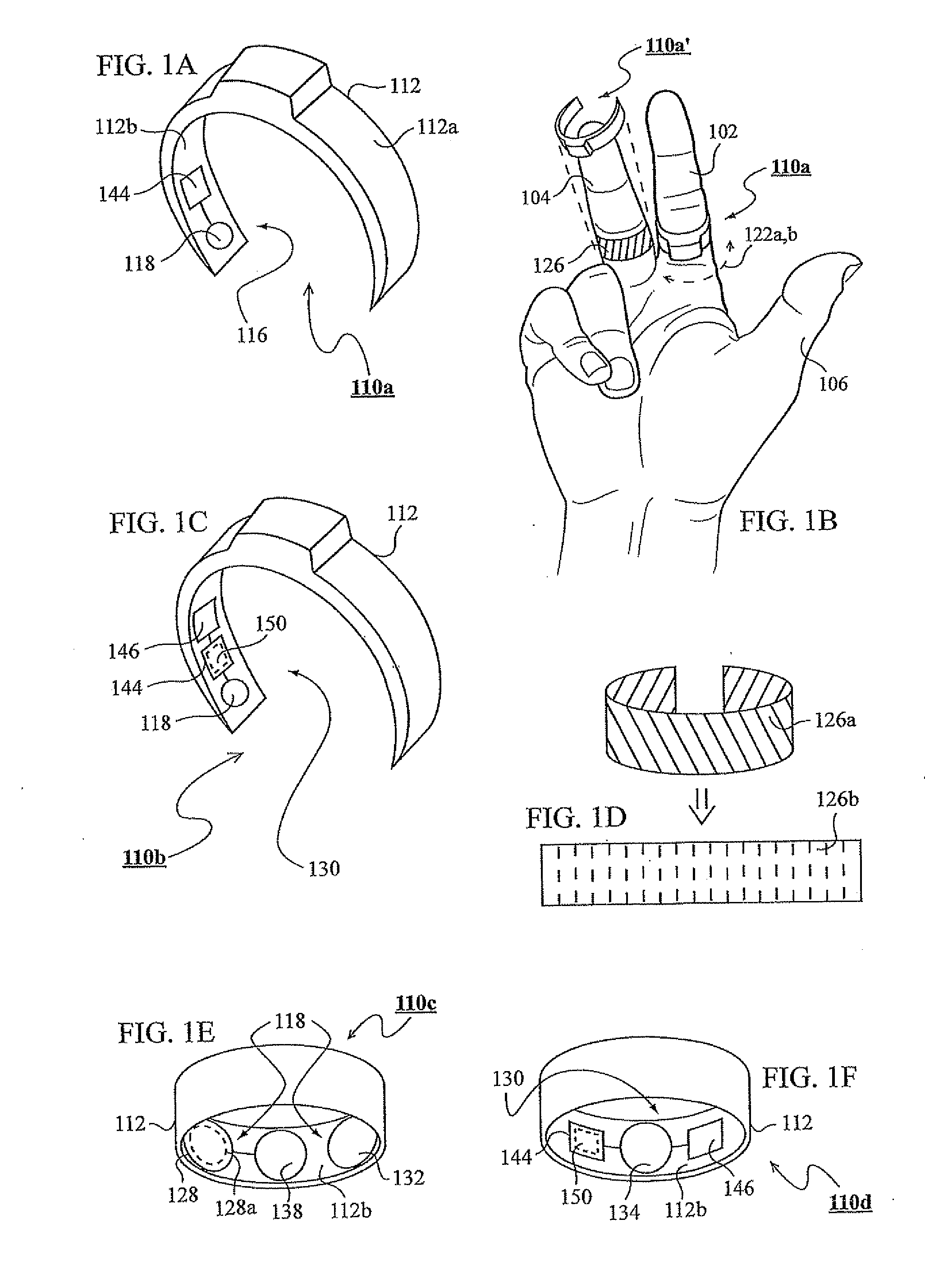
[0160]FIG. 1A shows a finger-worn device of the invention as a device 110a. Device 110a includes a rotatable section 112 which can be worn on and rotated around a finger. Device 110a further includes an indication mechanism 116 for indicating rotation (or “relative motion”) of section 112 around the finger. Section 112 is shown in FIG. 1A as a partial ring, however, it should be clear that this particular embodiment is by no means limiting, and that in some embodiments, section 112 is a full ring. In FIG. 1A, indication mechanism 116 includes a sensing mechanism 118. Sensing mechanism 118 may utilize any number of sensors generally directed to or facing the finger, such as being generally located at an internal side 112b of section 112. As section 112 rotates, mechanism 118 senses a different part on the curve of the finger (e.g. a sensor of mechanism 118 is facing a different part of the finger, specifically on the curve of the finger around which section 112 rotates). Accordingly,...

second embodiment

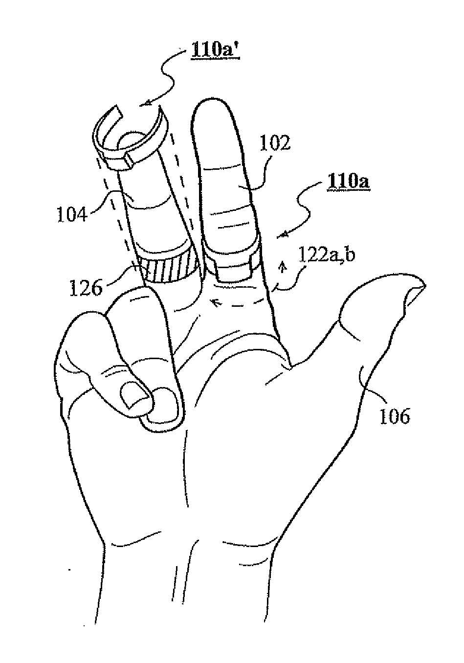
[0161]FIG. 1B shows device 110a exemplarily worn on an index finger 102. Rotation directions 122a,b are shown as directions in which device 110a can be rotated, such as by a thumb 106. FIG. 1B further shows a finger-worn device of the invention as a device 110a′ ready to be worn on a middle finger 104, specifically on a curve 126 of finger 104. Curve 126 is generally the curved surface of the finger at the circumference of the finger. When device 110a′ is worn on curve 126, the curve overlaps inner side 112b of section 112, from which sensing of the finger is performed. Accordingly, sensing is specifically of curve 126. The curve, as referred to herein, may include the entire circumference of the finger (full circle around the finger) or only a certain part of the circumference, such as only the curve of the front of the finger (shown in FIG. 1B). As section 112 rotates, a different part along curve 126 is sensed at any given time (such as by a sensor of mechanism 118 facing a diffe...

third embodiment

[0166]FIG. 1E shows a finger-worn device of the invention as a device 110c, similar to the previously described devices, in which a rotatable section 112 shown to have a shape of a full ring. A sensing mechanism 118 includes an optical sensing mechanism 128 (e.g. a photodiode). During rotation of section 112, indications of rotation may be obtained by sensed optical changes as sensed by mechanism 128 sensing the finger (see e.g. U.S. Pat. No. 6,259,108). Mechanism 118 may utilize a light source 132 (e.g. a light-emitting diode (LED)) to facilitate optical sensing of mechanism 128. In some embodiments, sensing mechanism 128 may utilize a passive infrared (PIR) sensor 128a for sensing the natural physiological radiation of infrared (IR) light from the finger, in which case light source 132 is not needed. In some embodiments, by utilizing a PIR sensor, mechanism 128 and accordingly mechanism 118, act as a passive indication mechanism (e.g. a passive indication mechanism 116a) where a p...


PUM


Abstract

Finger-worn user input devices and methods for operating same. In some embodiments, a device includes at least one rotatable section (112, 112′, 912) and an indication mechanism (116, 116a, 130, 516, 526, 616, 816, 826, 836, 1316, 1416, 1616, 2116, 2222, 2320, 2720, 3524) for indicating either a device use or a device state. In some embodiments, a device includes a stationary section (114), at least one rotatable section (112, 912) and an indication mechanism. In some embodiments, one or more rotatable sections are tiltable. In some embodiments, a device further includes one or more mechanisms selected from mechanisms used for sensing (118, 128, 128a, 134, 136, 1216), communication (140), power generation (616, 3342), light generation (526), vibration generation (516), reflection (816, 826, 836), illumination (3616), projection (3420), physical feedback (340) and magnetic influence (736).

Description

FIELD OF THE INVENTION[0001]The invention relates to in general to finger-worn user-input devices and in particular to finger-worn ring devices used for providing inputs to other devices or systems or used to provide indications to other devices or systems.BACKGROUND OF THE INVENTION[0002]Various finger-worn user-input devices are known. For example, U.S. Pat. No. 5,481,265 to Russell discloses some embodiments of an ergonomic customizable user / computer interface device. These embodiments include only ROM and EEPROM replaceable memory cartridges, for the purpose of user authentication and signals encoding. There is no mention of interface indicators of feedback mechanism. Also, the devices described do not reflect modern utilization of a vast selection of sensing mechanism types, and new engineering progress for generating and / or harvesting energy. Therefore, Russell's devices lack appropriate power sources for today's mobile markets. In addition, his devices have very limited modes...

Claims


Application Information

Patent Timeline
IPC IPC(8): G06F3/033
CPCG06F3/014G06F3/017G06F3/0219G06F3/0304G06F3/0312G06F2203/0339G06F3/03547G06F3/0362G06F3/042G06F3/0425G06F2203/0331G06F3/0338H04N9/3173
Inventor SHAI, SAAR
Owner RINGBOW LTD
Why Eureka
Try Eureka